Page 347 - Wago_Rail-MountedTerminalBlockSystems_Volume1_2015_US.pdf
P. 347

"

          X-COM -SYSTEM
                   ®
          Male Connectors with Snap-In Flanges                                                                      6
          Pin Spacing 5 mm                                                                                          345
          Pin spacing 5 mm / 0.197 in, gray                                     
          0.08 - 4 mm²  AWG 28 - 12
          500 V/6 kV/3 1                           <____________  L12 ____________>
                                                                          <
          I N 32 A 2                                Plate thickness 1–4 mm  4,25
                                                  <____ 1 8,5 ____>  > <__  > 2 <  <____ 17 ,1  ____>  >  >  <
          L 8 - 9 mm / 0.33 in 3                      1,4       ___>   <   6,7   <  5,9

                                                                          >  5,9
                                                  >  5,6 <       >  5,6 <
                                              L12 = pole no. x pin spacing + 10.2 mm
                                             Sheet metal cut-out (for female plugs without lock-
                                             ing levers)
                                             Male connectors with CAGE CLAMP  connection and   1 500 V = rated voltage
                                                                  ®
                                             snap-in flanges                       6 kV = rated surge voltage
                                                                                     3 = pollution degree
                                                                                  (see Section 14)
                                                                                2 See current-carrying capacity curve at
                                                                                  www.wago.com
                                                                                3 Strip length, see packaging or instructions.
                                      Pack.
          Pole No.      Item No.
                                      Unit
          Male connector with CAGE CLAMP  and snap-in
                                ®
          flanges,
          for mounting without tools,
          gray                                                                                                      6
            2           769-602/006-000  100
            3           769-603/006-000  100
            4           769-604/006-000  50
            5           769-605/006-000  25
            6           769-606/006-000  25
            7           769-607/006-000  25
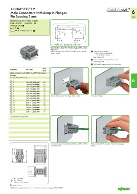
            8           769-608/006-000  25  Insert male connector into sheet metal cut-out.  Fix snap-in flange.
            9           769-609/006-000  20
            10          769-610/006-000  25
            11          769-611/006-000  25
            12          769-612/006-000  25
            13          769-613/006-000  15
            14          769-614/006-000  15
            15          769-615/006-000  10
          Accessories see page 344.


                                             For removal, insert operating tool (blade width 2.5 mm)   Press center part of connector. Then remove snap-in
                              <_______C _______>  into release slot.            flange.
                               <_____ B _____>
            <_____41 ,7 ______>  4,3  ___)  <_____37 ,2_____>
              _)


                                <___A ___>
                           <___30 ____>  <18,3>  _


           C = A + 14.3 mm
           B = A + 9.3 mm
           A = pole no. x pin spacing
          Dimensions in mm
          Certification organizations can be found in the overview on pages 622 and 623.
   342   343   344   345   346   347   348   349   350   351   352