
Page 349 - Wago_Rail-MountedTerminalBlockSystems_Volume1_2015_US.pdf
P. 349
X-COM -SYSTEM
®
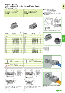
Male Headers with Solder Pins and Fixing Flanges 6
Pin Spacing 5 mm 347
Pin spacing 5 mm / 0.197 in, gray Pin spacing 5 mm / 0.197 in, gray 1 250 V/500 V = rated voltage
4 kV = rated surge voltage
250 V/4 kV/3 1 300 V, 20 AU 250 V/4 kV/3 1 600 V, 20 AU 3/2 = pollution degree
500 V/4 kV/2 1 300 V, 20 A2 500 V/4 kV/2 1 300 V, 20 A2 (also see Section 14)
I N 32 A 2 I N 32 A 2 2 See current-carrying capacity curve, page 362 and at
www.wago.com
1,6
L5
3,2 L4
18,7
8,5 11,6 15,5 7,1 10,5
3,5 L6
L6 = L4 + 2.6 mm
L5 = L5 + 6.6 mm
L4 = pole no. x pin spacing + 1.7 mm
Sheet metal cut-out for male header with fixing flanges
Pack. Pack.
Pole No. Item No. Pole No. Item No.
Unit Unit
Male header with straight solder pins and fixing Male header with angled solder pins and fixing
flanges, 1 x 1 mm, flanges, 1 x 1 mm,
gray gray
2 769-632/003-000 200 2 769-662/003-000 100 6
3 769-633/003-000 100 3 769-663/003-000 100
4 769-634/003-000 50 4 769-664/003-000 50
5 769-635/003-000 50 5 769-665/003-000 50
6 769-636/003-000 25 6 769-666/003-000 50
7 769-637/003-000 25 7 769-667/003-000 25
8 769-638/003-000 25 8 769-668/003-000 25
9 769-639/003-000 25 9 769-669/003-000 25 Male headers with preceding ground contact, with straight
10 769-640/003-000 25 10 769-670/003-000 25 solder pins and fixing flanges
769-632/003-036
11 769-641/003-000 25 11 769-671/003-000 25 769-633/003-036
12 769-642/003-000 25 12 769-672/003-000 25 769-634/003-036
13 769-643/003-000 15 13 769-673/003-000 15 769-635/003-036
14 769-644/003-000 15 14 769-674/003-000 15 769-636/003-036
15 769-645/003-000 15 15 769-675/003-000 15
Accessories
1-conductor female plug, 1-conductor female plug,
Pole Pole
1 straight 1 with lateral locking levers
gray 769-102 100 gray 769-102/021-000
50
Coding pin,
for coding female plugs
orange 769-435 100 (4x25)
9,75 9,95 9,75 9,95 Male header and 1-conductor female plug with locking
6,5 3,2 6,7 6,5 6,7 levers
2,6 3 22,2 2,6 3 3,2 22,2
2,8 3,7 2,8 3,7
11,4 6,9 18,3 8,7 11,4 6,9 18,3 8,7
3,6
L 5 5 5
L2 L 3
L3 L2
5,1 L3
5 2,8 5,1
3,9 3,9 2,8
7,8 7,8
2,6 2,6
1,2 1,2
L1 L1 Male header and 1-conductor female plug with lateral
L1 = L + 2.4 mm, L2 = L + 7 mm, L3 = L + 13.5 mm L1 = L + 2.4 mm, L2 = L + 7 mm, L3 = L + 13.5 mm locking levers
L = (pole no. - 1) x pin spacing + 6.2 mm L = (pole no. - 1) x pin spacing + 6.2 mm
Dimensions in mm Dimensions in mm
Certification organizations can be found in the overview on pages 622 and 623.