Page 352 - Wago_Rail-MountedTerminalBlockSystems_Volume1_2015_US.pdf
P. 352

X-COM -SYSTEM
                 ®
   6 Male Headers with Solder Pins and Rivet Fixing Flanges
  350 Pin Spacing 5 mm
        Pin spacing 5 mm / 0.197 in, gray
        250 V/4 kV/3 1
        500 V/4 kV/2 1
        I N 32 A 2


                                                                              1 250 V/500 V = rated voltage
                                                                                     4 kV = rated surge voltage
                                                                                      3/2 = pollution degree
                                                                                (also see Section 14)
                                                                              2 See current-carrying capacity curve at
                                                                                www.wago.com
                                    Pack.
        Pole No.      Item No.
                                    Unit
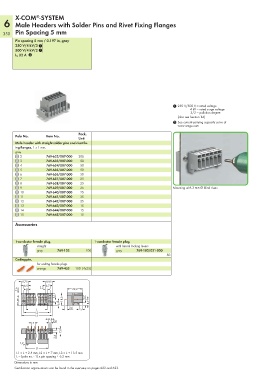
        Male header with straight solder pins and rivet fix-
        ing flanges, 1 x 1 mm,
        gray
          2           769-632/007-000  200
          3           769-633/007-000  50
          4           769-634/007-000  50
          5           769-635/007-000  50
          6           769-636/007-000  50
          7           769-637/007-000  25
          8           769-638/007-000  25
          9           769-639/007-000  25                                     Mounting with 3 mm Ø blind rivets
          10          769-640/007-000  25
          11          769-641/007-000  25
          12          769-642/007-000  25
          13          769-643/007-000  15
          14          769-644/007-000  15
          15          769-645/007-000  15
        Accessories


        1-conductor female plug,           1-conductor female plug,
             Pole                               Pole
             1   straight                       1    with lateral locking levers
                 gray      769-102     100           gray     769-102/021-000
                                                                           50
        Coding pin,
                 for coding female plugs
                 orange    769-435  100  (4x25)


           9,75       9,95
            6,5    3,2  6,7
         2,6  3                  22,2
                         3,15          3,7
         11,4              6,9  18,3    8,7
                                3,6
                 L                   5
                 L2
                 L3
                       5,1
               5         2,8
                            7,8
                          2,6
          1,2
                 L1
        L1 = L + 2.4 mm, L2 = L + 7 mm, L3 = L + 13.5 mm
        L = (pole no. - 1) x pin spacing + 6.2 mm
        Dimensions in mm
        Certification organizations can be found in the overview on pages 622 and 623.
   347   348   349   350   351   352   353   354   355   356   357