
Page 351 - Wago_Rail-MountedTerminalBlockSystems_Volume1_2015_US.pdf
P. 351
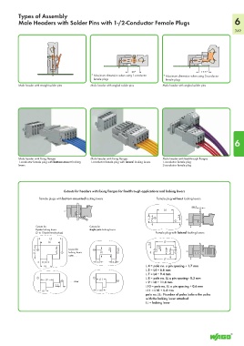
Types of Assembly
          Male Headers with Solder Pins with 1-/2-Conductor Female Plugs                                            6
                                                                                                                    349


                                                                 20*                               17.5*
                                              * Maximum dimension when using 1-conductor  * Maximum dimension when using 2-conductor
                                                 female plugs                       female plugs
          Male header with straight solder pins  Male header with angled solder pins  Male header with angled solder pins


                                                                                                                    6


          Male header with fixing flanges    Male header with fixing flanges    Male header with feedthrough flanges
          1-conductor female plug with bottom-mount locking   1-conductor female plug with lateral locking levers  1-conductor female plug
          levers                                                                2-conductor female plug


                                Cutouts for headers with fixing flanges for feedthrough applications and locking levers

                    Female plugs with bottom-mounted locking levers          Female plug without locking levers
                                                                                               max. 2
                                                                                              ____>  <_
                                                                                  L4
                                                                              <___   ___>
                                                                          <   >     14,8   7,9  >    <   3,4  >  <___
                  Cutouts for                Cutouts for
                  2-pole locking levers      single pole locking levers
                  (2- to 15-pole female plugs)                               Female plug with lateral locking levers

                    <_______   _____>
                          L5
                                                                                  L5
                         L4
                     <____   _____>                                        3,2  <____   _____>
                  <_            _>     14,8  <          >    Layout for   >    3,4  <__   4,8  >  <___   4,8  <__  <      >     11,8
                   21,5           locking levers   7,9  >    >                       6,8  >     <
                                  outer...
                                                                                    L7
                                                 6
                                                         6,2
                     11,3 <
                   >                          >    <  >    <                <_____   ______>
                     <   __>                                            L 4 = pole no. x pin spacing + 1.7 mm
                         L8
                                                                        L 5 = L4 + 6.6 mm
                                                                        L 7 = L4 + 9.4 mm
                                                  L11
                         L9
                     <__  __>                   <   >                   L 8 = pole no. LL x pin spacing - 0.3 mm

                                   . . . inner                          L 9 = L8 + 11.6 mm
                             3,2                                        L10 = pole no. LL x pin spacing + 0.6 mm
                            __>  <
                                                 L10
                   >     <                    >      <                  L11 = L10 + 5.4 mm
                      L8
                                                                        pole no. LL:  Number of poles before the poles
                                                                        with the locking lever attached
                                                                        LL = locking lever