
Page 360 - Wago_Rail-MountedTerminalBlockSystems_Volume1_2015_US.pdf
P. 360
"
X-COM -SYSTEM
®
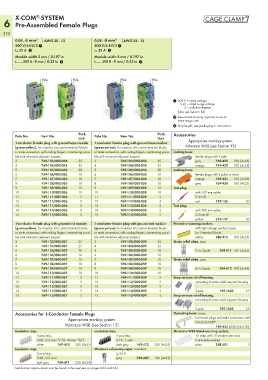
6 Pre-Assembled Female Plugs
358
0.08 - 4 mm² AWG 28 - 12 0.08 - 4 mm² AWG 28 - 12
500 V/6 kV/3 1 500 V/6 kV/3 1
I N 32 A 2 I N 32 A 2
Module width 5 mm / 0.197 in Module width 5 mm / 0.197 in
L 8 - 9 mm / 0.33 in 3 L 8 - 9 mm / 0.33 in 3
Po P
Pollole P Polole Pole Pole
1 1 1 1 1 1 1
1 500 V = rated voltage
6 kV = rated surge voltage
3 = pollution degree
(also see Section 14)
2 See current-carrying capacity curve at
www.wago.com
3 Strip length, see packaging or instructions.
Pack. Pack. Accessories
Pole No. Item No. Pole No. Item No.
Unit Unit
1-conductor female plug with ground base module 1-conductor female plug with ground base module Appropriate marking system:
(green-yellow), for insertion into carrier terminal blocks (green-yellow), for insertion into carrier terminal blocks Miniature WSB (see Section 13)
or male connectors, with coding fingers, commoning possi- or male connectors, with coding fingers, commoning possi- Locking lever,
ble with miniature adjacent jumpers ble with miniature adjacent jumpers female plugs with 1-pole
3 769-103/000-036 25 3 769-103/000-038 25 gray 769-428 100 (4x25)
4 769-104/000-036 25 4 769-104/000-038 25 orange 769-429 100 (4x25)
5 769-105/000-036 20 5 769-105/000-038 20 Locking lever,
6 769-106/000-036 10 6 769-106/000-038 10 female plugs with 2-poles or more
7 769-107/000-036 10 7 769-107/000-038 10 orange 769-431 100 (4x25)
8 769-108/000-036 10 8 769-108/000-038 10 gray 769-430 100 (4x25)
9 769-109/000-036 10 9 769-109/000-038 10 Test plug,
10 769-110/000-036 10 10 769-110/000-038 10 with 500 mm cable,
11 769-111/000-036 5 11 769-111/000-038 5 2 mm Ø
12 769-112/000-036 5 12 769-112/000-038 5 red 210-136 50
13 769-113/000-036 5 13 769-113/000-038 5 Test plug,
14 769-114/000-036 5 14 769-114/000-038 5 with 500 mm cable,
15 769-115/000-036 5 15 769-115/000-038 5 2.3 mm Ø
yellow 210-137 50
1-conductor female plug with ground end module 1-conductor female plug with ground end module Protective warning marker,
(green-yellow), for insertion into carrier terminal blocks (green-yellow), for insertion into carrier terminal blocks with high-voltage symbol, black,
or male connectors, with coding fingers, commoning possi- or male connectors, with coding fingers, commoning possi- for 5 terminal blocks
ble with miniature adjacent jumpers ble with miniature adjacent jumpers yellow 280-415 100 (4x25)
3 769-103/000-037 25 3 769-103/000-039 25 Strain relief plate, gray
4 769-104/000-037 25 4 769-104/000-039 25
5 769-105/000-037 20 5 769-105/000-039 20 2- to 3-pole 769-411 100 (4x25)
6 769-106/000-037 10 6 769-106/000-039 10
7 769-107/000-037 10 7 769-107/000-039 10 Strain relief plate, gray
8 769-108/000-037 10 8 769-108/000-039 10
9 769-109/000-037 10 9 769-109/000-039 10 4- to 5-pole 769-412 100 (4x25)
10 769-110/000-037 10 10 769-110/000-039 10
11 769-111/000-037 5 11 769-111/000-039 5 Snap-on type relief housing,
12 769-112/000-037 5 12 769-112/000-039 5 consisting of strain relief support/housing
13 769-113/000-037 5 13 769-113/000-039 5
14 769-114/000-037 5 14 769-114/000-039 5 3-pole 769-1603 25
15 769-115/000-037 5 15 769-115/000-039 5 Snap-on type relief housing,
consisting of strain relief support/housing
5-pole 769-1605 25
Accessories for 1-Conductor Female Plugs Operating lever, loose,
Appropriate marking system: for female plugs and male connectors with
®
Miniature WSB (see Section 13) CAGE CLAMP 769-4342000 (20x100)
Insulation stop, Insulation stop, Miniature WSB Quick marking system,
5 pcs/strip, 5 pcs/strip, 10 strips with 10 markers per card,
0.08 - 0.2 mm² “s” (0.14 mm² “f-st”) 0.75 - 1 mm² 5 mm wide markers
white 769-470 200 (8x25) dark gray 769-472 200 (8x25) plain 248-501 5
Insulation stop, Miniature adjacent jumper, insulated,
5 pcs/strip, I N 24 A
0.25 - 0.5 mm² gray 769-402 100 (4x25)
light gray 769-471 200 (8x25)
Certification organizations can be found in the overview on pages 622 and 623.