Page 473 - Wago_Rail-MountedTerminalBlockSystems_Volume1_2015_US.pdf
P. 473

"


          – Description and Handling –                                                                             11
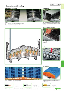
          Matrix patching assembly                                              Wiring space                        471


          Example                                                               Using terminal blocks with locking clips, the wiring space
          left:   Main cables fed through locking clips on the field side       between the terminal strips can be covered with a wiring
          right:   Control cables fed between locking clips                     duct cover.
          center:  Wiring of the patching sides

                                                                                CAGE CLAMP  connection
                                                                                             ®


                                                                                Terminating/removing conductors with (2.5 x 0.4) mm
                                                                                operating tool.


                                                                                Testing


                                                                                Special test contact for test plug 2.3 mm Ø.
                                                                                                                   11


                                                                                Ex i versions


          Marking coordinates via WMB Multi marking system.                     Blue terminal blocks for matrix patching are suitable for
                                                                                Ex i applications.


                                                              fine-stranded,                     fine-stranded,
                           fine-stranded,                     with ferrule 1                     with pin terminal
                           tip-bonded                         (gastight crimped)                 (gastight crimped)
          1 Max. cross section for uninsulated ferrules 1mm²/AWG 18, for insulated ferrules 0.75 mm²/AWG 20.
   468   469   470   471   472   473   474   475   476   477   478