
Page 282 - Destaco - Clamping Technology
P. 282
82L2G-2, 82L3.-2, 82L4.-2 series
Pneumatic Power Clamps | Technical Specifications
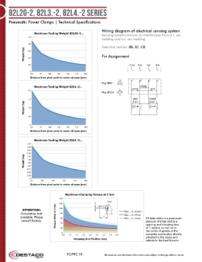
Wiring diagram of electrical sensing system
Maximum Tooling Weight 82L2G-2... Sensing system immune to interference from d.c. arc
1,0
welding and a.c. arc welding
0,8
Inductive version: B8, B7, C8
Weight [kg] 0,6 Pin Assignment
0,4
0,2 +brown black -blue white
1 4 3 2
0
50 75 100 125 150 175 200
Distance from pivot point to center of mass [mm]
1 4 1 4 3 2
Plug M8x1 2 3
Maximum Tooling Weight 82L3.-2... yellow
2,0 2 green red
Plug M12x1 3 1
4
1,5 open closed
S 0.1
S 0.2
Weight [kg] 1,0
0,5
0
50 75 100 125 150 175 200
Distance from pivot point to center of mass [mm]
Maximum Tooling Weight 82L4.-2...
2,75
2,50
2,25
2,00
Weight [kg] 1,50
1,75
1,25
1,00
0,75
0,50
0,25
0
75 100 125 150 175 200
Distance from pivot point to center of mass [mm]
Maximum Clamping Torque at 5 bar
140
Pivot
120 X
Torque (Nm) at 5 bar 82L3..., L1=99mm
ATTENTION: 100 82L4..., L1=104mm
Calculation tool 80
available. Please 60 L1 82L2..., L1=75mm All data refers to a pneumatic
consult factory. 40 pressure of 6 bar and to a
opening and closuring time
of 1 second, as well as to
20
the center of gravity of the
0
0,5 1,5 2,5 3,5 4,5 5,5 6,5 7,5 8,5 complete construction directly
attached to the clamp arm
Clamping Arm Position (mm)
related to the fixed fulcrum.
PC-PPC-19 Dimensions and technical information are subject to change without notice