
Page 280 - Destaco - Clamping Technology
P. 280
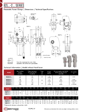
82L..-2... Series


      Pneumatic Power Clamps | Dimensions | Technical Specifications


                           Plan view         Dimensions of the
                       B31    B24a           driven shaft                     B1a     82L2*-2...

                                            SW        L17
                                       B23 max.                                         B3


                                                                                  + 0,02  22 ±0,1  B30  D4H7
                                                                        +0,05  0  5  0  +0,02  0  18
                                                                         5,05
                                       82L3*-2...      B1b
                           B24                         B1a

                      B5     B30
                 Pivot point
                                                                                    82L4*-2...    B1a
                L6  L8        B6                             B6a
                                     D1  (8x)  L8a  L2 max.  L18  D1a
                  L14                            B27
              L3  L7                                             L9
                                       D4H7  L9a
                    L9  B25  B7a            L1 max.  L19  B7
                     B5a             B5b                        D4aH7

                                                                            12  33


                                                              G

                                                              Connector (B): opening
                                                       B1      Connector (A): closing
             mm [INCH]  mm [INCH]

                         Power by compressed air, max. 6 bar
            THIRD ANGLE  FIRST ANGLE
                         Operation with oil-free air is permissible.
            PROJECTION  PROJECTION
      Technical Information | Model without Hand Lever

                         Max. holding    Clamping torque    Piston            Air consumption per double
           Model           torque        at 5 bar [72 psi]  Ø       Weight     stroke at 5 bar [72 psi]  Connection
                                                                                                         G
                                                                    kg [lbs]
                          Nm [lb ft]       Nm [lb ft]       mm                      dm3 [ft3]
                             75               25                      1,0              0,4
          82L2G-2…                                          25                                          G1/8
                            [55]              [18]                   [2.20]           [0.01]
          82L3G-2…          180               55            32        1,3              0,8              G1/8
          82L3N-2…          [133]             [41]                   [2.86]           [0.03]          1/8-18 NPT
          82L4G-2…          380               120           40        1,9              1,2              G1/4
          82L4N-2…          [280]             [89]                   [4.18]           [0.04]          1/4-18 NPT

                   B1   B1a  B1b             B3  B5  B5a  B5b  B6  B6a  B7        B7a**         B23    B24  B24a  B25     B27  B30        B31
          Model
                                                               ± 0,1  ± 0,1  max.           +0,1       ± 0,1
        82L2G-2…   32   34    -   3    4    4    4,5  7     -   25     -    53   60,5  53,5   -     -   44   15
         82L3.-2…  42   34   46    -   5    8    4,5  7    10   20    30    60   76,5  63,5  8    3,5   51   21
         82L4.-2…  45   40    -    -   6,5  6    4,5  10   10   25    35    74    88  69,5   9    3,5   57  26,5
                   D1   D1a  D4     D4a      L1    L2               L3  L6           L7           L8             L8a              L9              L9a**              L14      L17  L18  L19     SW
          Model
                             H7   H7   max.  max.       ± 0,05  + 0,1 ± 0,1 ± 0,1 ± 0,1  ± 0,1  ± 0,1   N9   h9
        82L2G-2…   M5   M5    5    -   183,5  104,5  67  17    28    5    -   18     -   14   8,5    -    -   9
         82L3.-2…  M5   M5    6    6   215    124   83   25    36    8   42   20    20   18   12,5  48   8   11
         82L4.-2…  M6   M6    6    6   245    141   92   30    40   10   50   20    25   20    16  58,5  8   16
      **Tolerance for distance to dowel hole ±0,02

                                          PC-PPC-17             Dimensions and technical information are subject to change without notice