
Page 251 - Mechatronics with Experiments
P. 251
MICROCONTROLLERS 237
TMR0IF Wake-up if in SLEEP mode
TMR0IE
TMR0IP
RBIF
RBIE
RBIP
INT0IF
INT0IE
INT1IF Interrupt to CPU
vector to location
INT1IE 0008h
Peripheral interrupt flag bit INT1IP
Peripheral interrupt enable bit INT2IF
Peripheral interrupt priority bit INT2IE
INT2IP
GIEH/GIE
TMR1IF
TMR1IE
TMR1IP IPE
XXXXIF IPEN
XXXXIE GIEL/PEIE
XXXXIP
IPEN
Additional peripheral interrupts
High priority interrupt generation
Low priority interrupt generation
Peripheral interrupt flag bit
Peripheral interrupt enable bit
Peripheral interrupt priority bit
Interrupt to CPU
TMR0IF
TMR0IE vector to location
0018h
TMR1IF TMR0IP
TMR1IE RBIF
TMR1IP RBIE
RBIP GIEL/PEIE
XXXXIF
XXXXIE INT1IF GIE/GIEH
XXXXIP INT1IE
INT1IP
Additional peripheral interrupts INT2IF
INT2IE
INT2IP
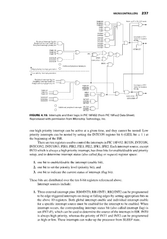
FIGURE 4.15: Interrupts and their logic in PIC 18F452 (from PIC 18Fxx2 Data Sheet).
Reproduced with permission from Microchip Technology, Inc.
one high priority interrupt can be active at a given time, and they cannot be nested. Low
priority interrupts can be nested by setting the INTCON register bit 6 (GIEL bit = 1)at
the beginning of the ISR.
There are ten registers used to control the interrupts in PIC 18F452: RCON, INTCON,
INTCON2, INTCON3, PIR1, PIR2, PIE1, PIE2, IPR1, IPR2. Each interrupt source, except
INT0 which is always a high priority interrupt, has three bits for enable/disable and priority
setup, and to determine interrupt status (also called flag or request) register space:
1. one bit to enable/disable the interrupt (enable bit),
2. one bit to set the priority level (priority bit), and
3. one bit to indicate the current status of interrupt (flag bit).
These bits are distributed over the ten 8-bit registers referenced above.
Interrupt sources include:
1. Three external interrupt pins: RB0/INT0, RB1/INT1, RB2/INT2 can be programmed
to be edge triggered interrupts on rising or falling edges by setting appropriate bits in
the above 10 registers. Both global interrupt enable and individual interrupt enable
for a specific interrupt source must be enabled for the interrupt to be enabled. When
interrupt occurs, the corresponding interrupt status bit (also called interrupt flag) is
set (INTxF), which can be used to determine the source of the interrupt in ISR. INT0
is always high priority, whereas the priority of INT1 and INT2 can be programmed
as high or low. These interrupts can wake-up the processor from SLEEP state.