
Page 250 - Mechatronics with Experiments
P. 250
236 MECHATRONICS
Main
Interrupt #1
task
Save status
ISR 1:
Interrupt #2
Save status
Interrupt
service
routine 1
ISR 2:
Interrupt
service
routine 2
Restore status
Restore status
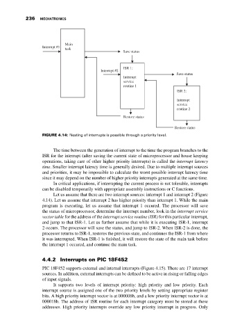
FIGURE 4.14: Nesting of interrupts is possible through a priority level.
The time between the generation of interrupt to the time the program branches to the
ISR for the interrupt (after saving the current state of microprocessor and house keeping
operations, taking care of other higher priority interrupts) is called the interrupt latency
time. Smaller interrupt latency time is generally desired. Due to multiple interrupt sources
and priorities, it may be impossible to calculate the worst possible interrupt latency time
since it may depend on the number of higher priority interrupts generated at the same time.
In critical applications, if interrupting the current process is not tolerable, interrupts
can be disabled temporarily with appropriate assembly instructions or C functions.
Let us assume that there are two interrupt sources: interrupt 1 and interrupt 2 (Figure
4.14). Let us assume that interrupt 2 has higher priority than interrupt 1. While the main
program is executing, let us assume that interrupt 1 occured. The processor will save
the status of microprocessor, determine the interrupt number, look in the interrupt service
vector table for the address of the interrupt service routine (ISR) for this particular interrupt,
and jump to that ISR-1. Let us further assume that while it is executing ISR-1, interrupt
2 occurs. The processor will save the status, and jump to ISR-2. When ISR-2 is done, the
processor returns to ISR-1, restores the previous state, and continues the ISR-1 from where
it was interrupted. When ISR-1 is finished, it will restore the state of the main task before
the interrupt 1 occured, and continue the main task.
4.4.2 Interrupts on PIC 18F452
PIC 18F452 supports external and internal interrupts (Figure 4.15). There are 17 interrupt
sources. In addition, external interrupts can be defined to be active in rising or falling edges
of input signals.
It supports two levels of interrupt priority: high priority and low priority. Each
interrupt source is assigned one of the two priority levels by setting appropriate register
bits. A high priority interrupt vector is at 000008h, and a low priority interrupt vector is at
000018h. The address of ISR routine for each interrupt category must be stored at these
addresses. High priority interrupts override any low priority interrupt in progress. Only