
Page 263 - Mechatronics with Experiments
P. 263
October 28, 2014 11:15 254mm×178mm
Printer: Yet to Come
JWST499-Cetinkunt
JWST499-c05
ELECTRONIC COMPONENTS FOR MECHATRONIC SYSTEMS 249
Current law states that the algebraic sum of currents at a node is equal to zero, which is a
statement of the “conservation of charge.” Voltage law states that the sum of voltages in a
loop is equal to zero, which is a statement of the “conservation of potential.” For instance
in Figure 5.2, Kirchoff’s current law states that
i − i − i = 0 (5.16)
2
3
1
and Kirchoff’s voltage law states that
V + V + V + V = 0 (5.17)
12 23 34 41
5.3 EQUIVALENT ELECTRICAL CIRCUIT METHODS
Quite often, we need to reduce a two-terminal circuit with multiple components into an
equivalent simpler circuit with a voltage source and an impedance or a current source and
an impedance. For now, assume that impedance is a generalized form of resistance.Two
of the most well-known equivalent circuit analysis methods are discussed below. These
methods are useful in determining input and output loading errors in coupled electrical
circuits, that is measurement errors introduced due to the effect of a measuring device in
an electrical circuit.
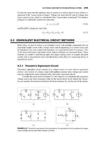
5.3.1 Thevenin’s Equivalent Circuit
Thevenin’s equivalent circuit consists of a voltage source in series with an equivalent
resistor. Any section of a linear circuit with multiple resistors (plus voltage and current
sources) components can be replaced with a Thevenin’s equivalent circuit.
Consider the circuit shown in Figure 5.3. Our objective is to determine the equivalent
voltage source and series resistance value for the circuit shown in the dotted line. Hence,
we can examine the interaction between the load resistance R and the rest of the circuit.
L
(a) (b)
(c) (d)
FIGURE 5.3: Thevenin’s equivalent circuit procedure. An equivalent circuit consists of an open
circuit voltage and an equivalent resistor in series.