
Page 264 - Mechatronics with Experiments
P. 264
JWST499-Cetinkunt
JWST499-c05
250 MECHATRONICS Printer: Yet to Come October 28, 2014 11:15 254mm×178mm
Thevenin’s equivalent circuit analysis requires the calculation of two parameters: V and
T
R eqv . The following are the standard steps to do that.
1. Identify the sub-circuit whose Thevenin’s equivalent circuit is to be determined.
Identify the two point terminals (a and b) out of the sub-circuit. Remove the load
resistor between the two points (Figure 5.3a).
2. Calculate the open circuit voltage between a and b, V = V , (Figure 5.3b).
T
ab
3. Short-circuit voltage sources (i.e., zero source) and disconnect all current sources
(open circuit the current sources) (Figure 5.3), and
4. calculate the equivalent series resistor (R eqv ) in the remaining circuit (excluding the
R ), R eqv (Figure 5.3c). The equivalent resistance of the circuit inside the dotted box
L
(as viewed from V ) is represented by R eqv and also called the output resistance of
ab
the sub-circuit. The circuit inside the dotted box can be viewed as a voltage source
plus a resistance the source has in addition to the load (Figure 5.3d).
As far as the two points a and b are concerned, the circuit inside the dotted block is
equivalent to a voltage source V = V ab and series resistor R eqv .
T
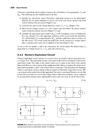
5.3.2 Norton’s Equivalent Circuit
Norton’s equivalent circuit consists of a current source in parallel with an equivalent resis-
tor (Figure 5.4). The equivalent resistor is the same as the resistor calculated in Thevenin’s
equivalent circuit. The value of the current source (i ) is same as the value of the current
N
that would flow in a short-circuit of the output terminals, that is to replace the output resis-
tance between points a and b with a short-circuit connection. The procedure for obtaining
Norton’s equivalent circuit is similar to the procedure for Thevenin’s equivalent circuit. The
conversions can be made between the equivalent Thevenin’s circuit and Norton’s circuit, that
is between two points in a circuit any voltage source with series resistance can be replaced
by an equivalent current source and parallel resistor, and visa versa. It can be shown that
V = i ⋅ R (5.18)
T N eqv
(a) (b)
(c) (d)
FIGURE 5.4: Norton’s equivalent circuit procedure. The equivalent circuit consists of a
current-source and an equivalent resistor in parallel.