Page 267 - Mechatronics with Experiments
P. 267

Printer: Yet to Come
                                                                                    October 28, 2014 11:15 254mm×178mm
                        JWST499-Cetinkunt
            JWST499-c05
                                                       ELECTRONIC COMPONENTS FOR MECHATRONIC SYSTEMS  253
                                          R                              R
                                                   L
                                      i(t)                          i(t)
                              V(t)                          V(t)                     C


                                             (a)                          (b)
                                                                           R
                                     A   R                          A
                                                   L
                                                                       B
                                        B                                     i(t)
                                             i(t)           V(t)                      C
                             V(t)


                                            (c)                          (d)
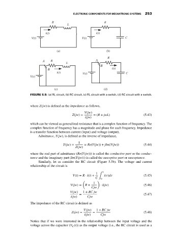
                             FIGURE 5.5: (a) RL circuit, (b) RC circuit, (c) RL circuit with a switch, (d) RC circuit with a switch.


                             where Z(jw) is defined as the impedance as follows,
                                                             V(jw)
                                                      Z(jw) =      = (R + jwL)                  (5.43)
                                                              i(jw)
                             which can be viewed as generalized resistance that is a complex function of frequency. The
                             complex function of frequency has a magnitude and phase for each frequency. Impedance
                             is a transfer function between current (input) and voltage (output).
                                  Admittance, Y(jw), is defined as the inverse of impedance,
                                                          1
                                                 Y(jw) =     = Re(Y(jw)) + jIm(Y(jw))           (5.44)
                                                        Z(jw)

                             where the real part of admittance (Re(Y(jw))) is called the conductive part or the conduc-
                             tance and the imaginary part (Im(Y(jw))) is called the susceptive part or susceptance.
                                  Similarly, let us consider the RC circuit (Figure 5.5b). The voltage and current
                             relationship of the circuit is
                                                                        t
                                                                    1
                                                      V(t) = R ⋅ i(t) +  i(  )d                 (5.45)
                                                                    C ∫ 0
                                                            (        )
                                                                   1
                                                     V(jw) =  R +      ⋅ i(jw)                  (5.46)
                                                                 Cjw
                                                     V(jw)  1 + RC jw
                                                          =                                     (5.47)
                                                     i(jw)     Cjw
                             The impedance of the RC circuit is defined as
                                                             V(jw)  1 + RC jw
                                                      Z(jw) =     =                             (5.48)
                                                             i(jw)     Cjw
                             Notice that if we were interested in the relationship between the input voltage and the
                             voltage across the capacitor (V (t)) as the output voltage (i.e., the RC circuit is used as a
                                                      C
   262   263   264   265   266   267   268   269   270   271   272