
Page 262 - Mechatronics with Experiments
P. 262
JWST499-Cetinkunt
JWST499-c05
248 MECHATRONICS Printer: Yet to Come October 28, 2014 11:15 254mm×178mm
Energy stored in a capacitor can be calculated as follows,
Q
dW = V ⋅ dQ = dQ (5.10)
C
1 Q 2
W = (5.11)
2 C
and the W ≤ W max , where W max is the maximum energy storage capacity of the capacitor,
1 2
W = C ⋅ V (5.12)
max max
2
Notice that capacitors block the DC voltage and pass the AC voltage. In other words,
the DC voltage will build a potential difference in the capacitor until they are equal,
provided that the DC source voltage is below the break-down voltage of the capacitor. The
AC voltage simply alternates the charge and discharge of the capacitor. Unlike the DC
component, which is blocked by the capacitor, the AC component of the voltage is passed.
An ideal inductor generates a potential difference proportional to the rate of change
of current passing through it
di(t)
V 12 = L ⋅ (5.13)
dt
where L is called the inductance. Notice that, regardless of the direction of current (i > 0or
i < 0), the voltage across the inductor is proportional to the rate of change of the current.
Let V and V be the voltages at point 1 and 2 across the inductor with reference to
10 20
ground. Then,
di
V > V when > 0 (5.14)
10 20
dt
di
V 10 < V 20 when < 0 (5.15)
dt
The inductor is made with a coil of a conductor around a core, like a solenoid. The
core can be a magnetic or an insulating material. The inductance value, L, is a function
of permeability of the core material, number of turns in the coil, cross-sectional area, and
length. Permeability of a material is a measure of its ability to conduct electromagnetic
fields. It is analogous to the electrical conductivity. If the material composition of the space
around an inductor changes, that is due to motion of device components in a solenoid, the
inductance changes.
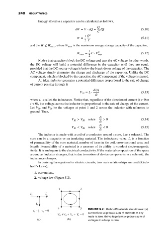
In deriving the equation for electric circuits, two main relationships are used (Kirch-
hoff’s Laws);
1. current law,
2. voltage law (Figure 5.2).
1 2
i i
1 2
i
3
4 3
i − i − = 0 FIGURE 5.2: Kirchhoff’s electric circuit laws: (a)
i
1 2 3
V + V + V + V = 0 current law: algebraic sum of currents at any
12 23 34 41
node is zero. (b) voltage law: algebraic sum of
(a) (b) voltages in a loop is zero.