
Page 296 - Mechatronics with Experiments
P. 296
JWST499-Cetinkunt
JWST499-c05
282 MECHATRONICS Printer: Yet to Come October 28, 2014 11:15 254mm×178mm
5.6 OPERATIONAL AMPLIFIERS
Operational amplifiers (op-amps) were first developed in the late 1940s. Today, op-amps
are linear integrated circuits which are low cost, reliable, and hundreds of millions of units
are made per year. As the name implies, an op-amp performs an operational amplification
function where the operation may be add, subtract, multiply, filter, compare, convert, and
so on. Op-amp is a device with a very high open loop gain (ideally infinity, in reality finite
but very large). The main function of an op-amp is often defined by external feedback com-
ponents. There are a number of operational amplifiers manufactured by multiple vendors
under licence. For instance, op-amp 741 is available under the trade names LM741, NE741,
μA741 by different manufacturers. LM117/LM217/LM317 is a higher performance ver-
sion of 741. LM117, LM217, LM317 are rated for military, industrial and commercial
applications, respectively. The 301, LM339, LM311 (comparator IC chip), LM317 (volt-
age regulator), 555 timer IC chip, XR2240 counter/timer are widely used op-amps. The
integrated circuit design incorporates multiple discrete devices (transistors, resistors, capac-
itors, diodes) into one compact chip which is typically in dual-inline-package (DIP) form.
The 741 op-amp has 17 BJT transistors, 12 resistors, 1 capacitor, and 4 diodes.
Note that the actual internal component count and design may vary from manufacturer to
manufacturer. The coding standard used to identify an op-amp includes the manufacturer
code, op-amp functional code, rating for commercial or military use, and mechanical
package form (i.e., DIP). In order to use an op-amp in a design, the designer needs the
physical size, functionality described in the data sheet, and pinout information of the op-
amp. With the wide availability and proven designs of integrated circuit (IC) op-amps, it
is very rare that one designs circuits from discrete components (using transistors, resistors,
capacitors, etc.) for analog signal processing purposes. For almost every analog signal
processing need, there is an IC op-amp available in the market. Most often, the designer
does not need to know all the internal circuit details of the IC op-amp. The characteristics
of the IC op-amp that are needed are its input–output function (i.e., low pass filter), gain,
bandwidth and input/output impedances. Most IC op-amp packages include multiple stages
in the IC design, that is input stage generally includes a differential amplifier for its high
input impedance, followed by an intermediate gain stage and finally an output stage.
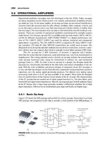
5.6.1 Basic Op-Amp
Figure 5.23 shows the DIP package and symbol for a basic op-amp. Notice that in an 8-pin
DIP package, the integrated circuit chip is actually a small portion of the DIP package. A
Positive power supply
Balance 1 8 NC voltage terminal
V+
-In
2 7 V+ Inverting input
- terminal (-In) v - - v 0
+ Non-inverting +
+In Output Output
3 6 input terminal v + terminal
(+In)
V-
V- 4 5 Balance Negative power supply
voltage terminal
(a) (b) (c)
FIGURE 5.23: Operation amplifier: (a) op-amp DIP-packages, (b) op-amp pins, (c) op-amp
symbol.