Page 297 - Mechatronics with Experiments
P. 297

October 28, 2014 11:15 254mm×178mm
                                         Printer: Yet to Come
            JWST499-c05
                        JWST499-Cetinkunt
                                                       ELECTRONIC COMPONENTS FOR MECHATRONIC SYSTEMS  283
                                             _
                                             +


                                                  _   Z out
                               +
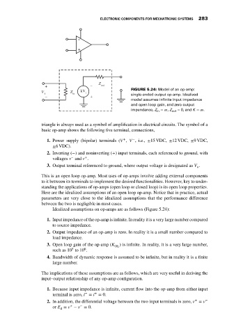
                             V            Z   kV i                  FIGURE 5.24: Model of an op-amp:
                               i           in                       single-ended output op-amp. Idealized
                               _                  +
                                                                    model assumes infinite input impedance
                                                                    and open loop gain, and zero output
                                                                                 =∞, Z  = 0, and K =∞.
                                                                    impendance, Z in  out

                             triangle is always used as a symbol of amplification in electrical circuits. The symbol of a
                             basic op-amp shows the following five terminal, connections,

                                                                     −
                                                                 +
                                1. Power supply (bipolar) terminals (V , V , i.e., ±15 VDC, ±12 VDC, ±9 VDC,
                                  ±6 VDC).
                                2. Inverting (−) and noninverting (+) input terminals, each referenced to ground, with
                                          −
                                                +
                                  voltages v and v .
                                3. Output terminal referenced to ground, where output voltage is designated as V .
                                                                                                o
                             This is an open loop op-amp. Most uses of op-amps involve adding external components
                             to it between its terminals to implement the desired functionalities. However, key to under-
                             standing the applications of op-amps (open loop or closed loop) is its open loop properties.
                             Here are the idealized assumptions of an open loop op-amp. Notice that in practice, actual
                             parameters are very close to the idealized assumptions that the performance difference
                             between the two is negligible in most cases.
                                  Idealized assumptions on op-amps are as follows (Figure 5.24):

                                1. Input impedance of the op-amp is infinite. In reality it is a very large number compared
                                  to source impedance.
                                2. Output impedance of an op-amp is zero. In reality it is a small number compared to
                                  load impedance.
                                3. Open loop gain of the op-amp (K  ) is infinite. In reality, it is a very large number,
                                                             OL
                                                6
                                          5
                                  such as 10 to 10 .
                                4. Bandwidth of dynamic response is assumed to be infinite, but in reality it is a finite
                                  large number.
                             The implications of these assumptions are as follows, which are very useful in deriving the
                             input–output relationship of any op-amp configuration.

                                1. Because input impedance is infinite, current flow into the op-amp from either input
                                                −
                                                    +
                                  terminal is zero, i = i = 0.
                                                                                                +
                                2. In addition, the differential voltage between the two input terminals is zero, v = v −
                                              −
                                          +
                                  or E = v − v = 0.
                                      d
   292   293   294   295   296   297   298   299   300   301   302