Page 293 - Mechatronics with Experiments
P. 293

October 28, 2014 11:15 254mm×178mm
                                         Printer: Yet to Come
            JWST499-c05
                        JWST499-Cetinkunt
                                                       ELECTRONIC COMPONENTS FOR MECHATRONIC SYSTEMS  279
                             The current through the R ,
                                                  E
                                                             V out  V − 0.6
                                                                    in
                                                        i =      =                             (5.162)
                                                         E
                                                             R E     R E
                             and the current through the collector,
                                                       i =    ⋅ i B                            (5.163)
                                                       C
                                                       i = i + i = (   + 1) ⋅ i B              (5.164)
                                                       E
                                                           C
                                                               B
                                                           (   + 1)
                                                         =       i C                           (5.165)
                                                               
                             and
                                                                       V − 0.6
                                                                        in
                                                    i =      i =                               (5.166)
                                                              E
                                                     C
                                                            + 1      + 1  R E
                             as long as the transistor is not saturated, (V > V + 0.2), the current output (i )ispro-
                                                                 C
                                                                                             E
                                                                      E
                             portional to the base voltage. This circuit does not have any voltage gain, but it does have
                             current gain, and hence power gain, between input and output signals.
                                  Note that
                                                        V = V  BE  + V E                       (5.167)
                                                         in
                                                         V = V − V BE  ≥ 0.0                   (5.168)
                                                               in
                                                          E
                                                        V = V  CE  + V E                       (5.169)
                                                          C
                             The voltage at the emitter follows the base voltage. Current through the collector and emitter
                             is proportional to the base voltage.
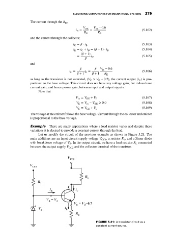
                             Example     There are many applications where a load resistor varies and despite these
                             variations it is desired to provide a constant current through the load.
                                  Let us modify the circuit of the previous example as shown in Figure 5.21. The
                             main additions are an input circuit supply voltage V CC1 , a resistor R , and a Zener diode
                                                                                     1
                             with breakdown voltage of V . In the output circuit, we have a load resistor R connected
                                                                                           L
                                                     Z
                             between the output supply V CC2  and the collector terminal of the transistor.


                                                                    FIGURE 5.21: A transistor circuit as a
                                                                    constant current-source.
   288   289   290   291   292   293   294   295   296   297   298