Page 452 - Mechatronics with Experiments
P. 452

JWST499-Cetinkunt
            JWST499-c07
                       438   MECHATRONICS  Printer: Yet to Come                      October 9, 2014 8:41 254mm×178mm
                              Mechanical     Pump        Hydraulic
                                power                     power

                                            Hydraulic
                                            fluid inlet
                                              (a)

                                                           P
                                              l             2
                                                  P 3

                                                           P 1
                                            P  < P 1
                                             3
                                                          T
                                              (b)
                                                           P 2


                                                  P 3
                                             P  > P 1      P 1
                                              3
                                          P = P  + P spring
                                              2
                                           3
                                                          T
                                              (c)
                                                           P 2
                                                               P max
                                                  P 3
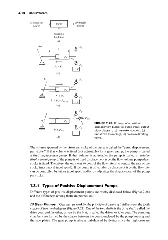
                                                                    FIGURE 7.25: Concept of a positive
                                                           P 1      displacement pump: (a) pump input–output
                                            P 3  ≤ P max            block diagram, (b) in-stroke (suction), (c)
                                                                    out-stroke (pumping), (d) pressure limiting
                                              (d)                   valve.

                              The volume spanned by the piston per stoke of the pump is called the “pump displacement
                              per stroke.” If that volume is fixed (not adjustable) for a given pump, the pump is called
                              a fixed displacement pump. If that volume is adjustable, the pump is called a variable
                              displacement pump. If the pump is of fixed displacement type, the flow volume pumped per
                              stroke is fixed. Therefore, the only way to control the flow rate is to control the rate of the
                              stroke (mechanical input speed). If the pump is of variable displacement type, the flow rate
                              can be controlled by either input speed and/or by adjusting the displacement of the pump
                              per stroke.


                              7.3.1 Types of Positive Displacement Pumps
                              Different types of positive displacement pumps are briefly discussed below (Figrue 7.26)
                              and the differences among them are pointed out.


                              (i) Gear Pumps   Gear pumps work by the principle of carrying fluid between the tooth
                              spaces of two meshed gears (Figure 7.27). One of the two shafts is the drive shaft, called the
                              drive gear, and the other, driven by the first, is called the driven or idler gear. The pumping
                              chambers are formed by the spaces between the gears, enclosed by the pump housing and
                              the side plates. The gear pump is always unbalanced by design since the high-pressure
   447   448   449   450   451   452   453   454   455   456   457