Page 451 - Mechatronics with Experiments
P. 451

JWST499-Cetinkunt
                                         Printer: Yet to Come
            JWST499-c07
                                                                                     October 9, 2014 8:41 254mm×178mm
                                                            ELECTROHYDRAULIC MOTION CONTROL SYSTEMS  437
                                2000                                                         10000
                                1000                                                         5000
                                 500
                                 200              SAE 10W                                    1000
                                 100                                                         500
                                 50                                                          250
                                 20                                 SAE 40   SAE 70          100
                                 10 8 6                  Hydraulic fluid MIL-0-5606  Bunker “C” & SAE 50  50
                                                                             SAE 60
                               Kinetic viscosity   4 3  JP-5  Diesel fuel  AN-0-9 grade 1010  SAE 10  SAE 20  40  Saybolt universal seconds
                                                                          SAE 30
                                                                         SAE 10
                                                                                             35
                                                                       MIL-L-7808
                                                     Kerosene
                                                                    No. 4 fuel oil
                                 1.5 2  Aviation gasoline–average  No. 2 fuel oil  No. 3 fuel oil
                                                JP-5– average
                                  1
                                  .9
                                  .8
                                  .7
                                  .6
                                     –60  –40 –20  0  20  40  60 80 100  150  200  250  300  350  400 500
                                                           Temperature °F
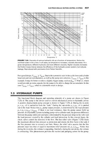
                             FIGURE 7.24: Viscosity of various hydraulic oils as a function of temperature. Notice the
                             nonlinear scale in the y-axis. In all cases, as temperature increases, viscosity decreases. At a
                             given temperature, different hydraulic oils have different viscosity. Higher viscosity increases
                             the friction losses (hence reduces the efficiency of the hydraulic power system), but reduces
                             leakage. Reproduced with permission from Parker Hannifin.


                             For agooddesign, V charge  ≥ V disch .Duetothesymmetricratiointhecycletimesandcylinder
                             head-end and rod-end diameters, as well as the pump size selection, V charge  = V disch  in this
                                                                                             3
                             example. It may be better to select a slightly bigger pump, such as Q  = 50 in ∕s, which
                                                                                    ave
                             would provide an extra capacity for the pump to be able to charge the accumulator. In this
                             case V    > V    , which is a desirable result in design.
                                   charge  disch

                      7.3 HYDRAULIC PUMPS

                             The functional block diagram and operating principle of a pump are shown in Figure
                             7.25a–d. The pump is the device used to convert mechanical power to hydraulic power.
                             A positive displacement pump concept is shown in Figure 7.25b–d. During the in-stoke
                             p < p , oil is sucked in from the “tank.” During the out-stroke p ≥ p , oil is pushed
                              3    1                                                3   2
                             out to the load. Notice that p , pump output pressure, is determined by the load pressure
                                                     3
                             p ≈ p = p    + p    . If there is no load resistance, then the pump cannot build up
                              3    2   load  spring
                             pressure. In a hydraulic system including pump-valve-cylinder-tank, the pressure difference
                             between the pump outlet port and tank is determined by the pressure drop on the valve and
                             the load pressure created by the cylinder and load interaction. In this concept figure, the
                             check valves control the direction of the flow. The line relief valve (Figure 7.25d) limits
                             the maximum allowed line pressure as protection and returns the flow back to the tank if
                             the line pressure tries to exceed a set limit. Hence, the relief valve assures that the line
                             pressure stays less than or equal to maximum relief pressure set, p ≤ p max . Notice that
                                                                                    3
                             during the in-stroke, the volume is expanding. Similarly, during the out-stroke, the volume
                             is contracting. This phenemenon provides the suction and pumping action for the pump.
   446   447   448   449   450   451   452   453   454   455   456