
Page 447 - Mechatronics with Experiments
P. 447
Printer: Yet to Come
October 9, 2014 8:41 254mm×178mm
JWST499-Cetinkunt
JWST499-c07
ELECTROHYDRAULIC MOTION CONTROL SYSTEMS 433
Pressure Transmission (pipe) loss
Valve loss
Transmission (pipe) loss
Actuator loss
Pressure at pump outport Pressure at valve inport Pressure at valve outport Pressure at actuator outport Pressure at load Pressure delivered
to load
Pump Pipe Valve Pipe Actuator Load Component location
(a)
Q
Valve 2
M P
W
in
Valve 1
T
(b)
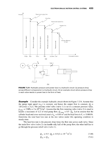
FIGURE 7.21: Hydraulic pressure and power loss in a hydraulic circuit: (a) pressure drop
across different components in a hydraulic circuit, (b) an example circuit where pressure drop
in each valve results in power loss in the form of heat.
Example Consider the example hydraulic circuit shown in Figure 7.21b. Assume that
the pump input speed (w ) is constant, and hence the output flow is constant, Q =
in
p
120 l∕min = 2l∕s. The pressure relief valve (valve 1) is set to a constant pressure value,
2
6
p relief = 2MPa = 2 × 10 N∕m . Assume that the flow metering valve (valve 2) is sized to
handle a maximum of 1∕2 of total pump flow, Q v,max = 0.5 ⋅ Q . Let us assume that the
p
2
cylinder head-end cross-sectional area is A he = 0.01 m and the load force is F = 10 000 N.
l
Determine the total heat loss rate at the two valves under this operating condition in
steady-state.
The heat loss rate is the pressure drop times the flow rate across each valve. Since
the main flow valve (valve 2) can handle only half of the pump flow, the other half has to
go through the pressure relief valve (valve 1).
3
Q v1 = 0.5 ⋅ Q = 1.0l∕s = 10 −3 m ∕s (7.60)
p
Q v2 = Q v1 (7.61)