
Page 449 - Mechatronics with Experiments
P. 449
October 9, 2014 8:41 254mm×178mm
Printer: Yet to Come
JWST499-c07
JWST499-Cetinkunt
ELECTROHYDRAULIC MOTION CONTROL SYSTEMS 435
Pumps Valves (types) Pressure compensated
Hydraulic pump
fixed displacement Check Solenoid, single winding
unidirectional
On/off
Hydraulic motor (manual shut-off) Reversing motor M
variable displacement
unidirectional Pressure releif Pilot pressure
with drain remote supply
Motors and Cylinders
Pilot pressure
internal supply
Pressure reducing
Hydraulic motor
fixed displacement with drain
Lines
Flow control - adjustable Line, working (main)
Hydraulic motor
variable displacement non-compensated
Line, pilot (for control)
Flow control - adjustable
Single acting cylinder
Temperature & pressure
Double acting cylinder compensated Line, liquid drain
Single end rod cylinder hydraulic
Two position Flow, direction of
Double end rod cylinder pneumatic
Two connection
Adjustable cushion
Advance only Two position Lines crossing
Three connection
Differntial piston
Lines joining
Two position
Miscellaneous units
Four connection
Three position Lines with fixed
Electric motor M Four connection restriction
Two position
Accumalator, spring Lines (flexible)
In transition
loaded
Accumalator, Station, testing,
Valves capable of
gas charged measurement or power
proportional positioninng
take-off
Heater
Valves Temperature cause or
Cooler (method of actuation) effect
Spring
Temperature vented
controller Reservoir
Manual
Filter strainer pressurized
Push button
Pressure switch
Line, to reservoir
Push pull lever above fluid level
Pressure indicator
Pedal or tradle
Temperature indicator
Mechanical
Direction of shaft Line, to reservoir
rotation below fluid level
Assume arrow on Detent
near side of shaft
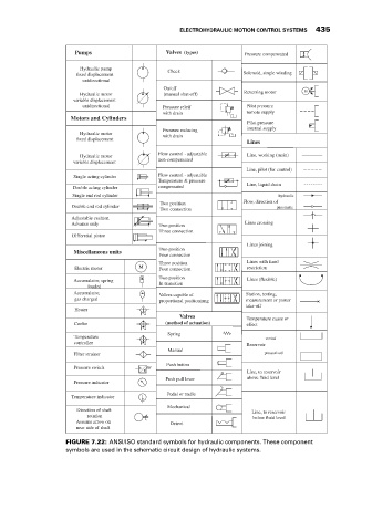
FIGURE 7.22: ANSI/ISO standard symbols for hydraulic components. These component
symbols are used in the schematic circuit design of hydraulic systems.