Page 450 - Mechatronics with Experiments
P. 450

JWST499-Cetinkunt
            JWST499-c07
                       436   MECHATRONICS  Printer: Yet to Come                      October 9, 2014 8:41 254mm×178mm
                                                                                           y ·


                                                  Q          Main valve
                                                   acc
                              w (t)        Q P p        Q V
                                            P
                               in
                                                   Q r                                       A B

                                             P relief
                                                                                             A A

                                    T

                                           y ·


                                                                                        s
                                                     7.5       15        22.5     30


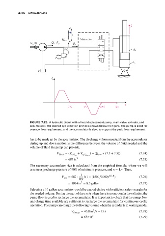
                              FIGURE 7.23: A hydraulic circuit with a fixed displacement pump, main valve, cylinder, and
                              accumulator. The desired cyclic motion profile is shown below the figure. The pump is sized for
                              average flow requirement, and the accumulator is sized to support the peak flow requirement.


                              has to be made up by the accumulator. The discharge volume needed from the accumulator
                              during up and down motion is the difference between the volume of fluid needed and the
                              volume of fluid the pump can provide,

                                              V disch  = (V cyl up  + V cyl down ) − (Q ave  ∗ (7.5 + 7.5))  (7.74)
                                                   = 687 in 3                                    (7.75)
                              The necessary accumulator size is calculated from the empirical formula, where we will
                              assume a precharge pressure of 90% of minimum pressure, and n = 1.4. Then,
                                                             1                1∕1.4
                                                 V   = 687 ⋅   ∕(1 − (1500∕3000)  )              (7.76)
                                                   acc
                                                            0.9
                                                             3
                                                     = 1954 in = 8.5 gallon                      (7.77)
                              Selecting a 10 gallon accumulator would be a good choice with sufficient safety margin for
                              the needed volume. During the part of the cycle when there is no motion in the cylinder, the
                              pump flow is used to recharge the accumulator. It is important to check that the pump flow
                              and charge time available are sufficient to recharge the accumulator for continuous cyclic
                              operation. The pump can charge the following volume when the cylinder is in waiting mode,
                                                                    3
                                                       V charge  = 45.8in ∕s ∗ 15 s              (7.78)
                                                             = 687 in 3                          (7.79)
   445   446   447   448   449   450   451   452   453   454   455