
Page 446 - Mechatronics with Experiments
P. 446
JWST499-Cetinkunt
JWST499-c07
432 MECHATRONICS Printer: Yet to Come October 9, 2014 8:41 254mm×178mm
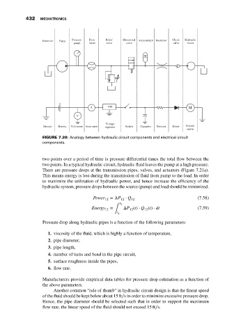
Pressure Flow Relief Directional Check Hydraulic
Reservoir Pump Accumulator Restrictor
gauge meter valve valve valve motor
A VRL M
V
Voltage
Ground Battery Volt meter Amp meter regulator Switch Capacitor Resistor Diode Electric
motor
FIGURE 7.20: Analogy between hydraulic circuit components and electrical circuit
components.
two points over a period of time is pressure differential times the total flow between the
two points. In a typical hydraulic circuit, hydraulic fluid leaves the pump at a high pressure.
There are pressure drops at the transmission pipes, valves, and actuators (Figure 7.21a).
This means energy is lost during the transmission of fluid from pump to the load. In order
to maximize the utilization of hydraulic power, and hence increase the efficiency of the
hydraulic system, pressure drops between the source (pump) and load should be minimized.
Power 12 =ΔP 12 ⋅ Q 12 (7.58)
t 2
Energy = ΔP (t) ⋅ Q (t) ⋅ dt (7.59)
12 ∫ 12 12
t 1
Pressure drop along hydraulic pipes is a function of the following parameters:
1. viscosity of the fluid, which is highly a function of temperature,
2. pipe diameter,
3. pipe length,
4. number of turns and bend in the pipe circuit,
5. surface roughness inside the pipes,
6. flow rate.
Manufacturers provide empirical data tables for pressure drop estimation as a function of
the above parameters.
Another common “rule of thumb” in hydraulic circuit design is that the linear speed
of the fluid should be kept below about 15 ft∕s in order to minimize excessive pressure drop.
Hence, the pipe diameter should be selected such that in order to support the maximum
flow rate, the linear speed of the fluid should not exceed 15 ft∕s.