Page 445 - Mechatronics with Experiments
P. 445

Printer: Yet to Come
                                                                                     October 9, 2014 8:41 254mm×178mm
            JWST499-c07
                        JWST499-Cetinkunt
                                                            ELECTROHYDRAULIC MOTION CONTROL SYSTEMS  431
                                          l
                                      Q
                                       0      d


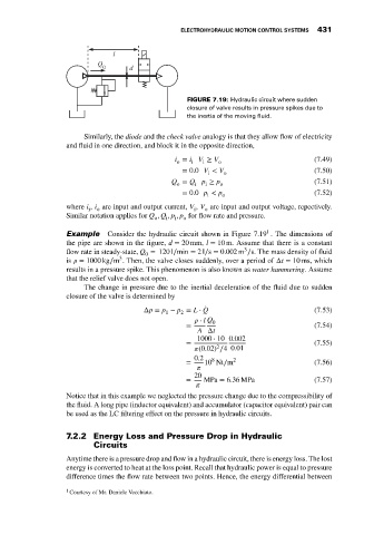
                                                              FIGURE 7.19: Hydraulic circuit where sudden
                                                              closure of valve results in pressure spikes due to
                                                              the inertia of the moving fluid.

                                  Similarly, the diode and the check valve analogy is that they allow flow of electricity
                             and fluid in one direction, and block it in the opposite direction,
                                                           i = i V ≥ V o                        (7.49)
                                                                  i
                                                           o
                                                               i
                                                             = 0.0 V < V o                      (7.50)
                                                                    i
                                                          Q = Q p ≥ p  o                        (7.51)
                                                                   i
                                                           o
                                                                i
                                                             = 0.0 p < p                        (7.52)
                                                                   i   o
                             where i , i are input and output current, V , V are input and output voltage, repectively.
                                   i  o                         i  o
                             Similar notation applies for Q , Q , p , p for flow rate and pressure.
                                                     o  i  i  o
                                                                                   1
                             Example     Consider the hydraulic circuit shown in Figure 7.19 . The dimensions of
                             the pipe are shown in the figure, d = 20 mm, l = 10 m. Assume that there is a constant
                                                                             3
                             flow rate in steady-state, Q = 120 l∕min = 2l∕s = 0.002 m ∕s. The mass density of fluid
                                                   0
                                            3
                             is    = 1000 kg∕m . Then, the valve closes suddenly, over a period of Δt = 10 ms, which
                             results in a pressure spike. This phenomenon is also known as water hammering. Assume
                             that the relief valve does not open.
                                  The change in pressure due to the inertial deceleration of the fluid due to sudden
                             closure of the valve is determined by
                                                  Δp = p − p = L ⋅ Q ̇                          (7.53)
                                                        1   2
                                                                   ⋅ l Q 0
                                                              =                                 (7.54)
                                                                 A Δt
                                                                 1000 ⋅ 10 0.002
                                                              =                                 (7.55)
                                                                      2
                                                                  (0.02) ∕4 0.01
                                                                0.2  8    2
                                                              =    10 Nt∕m                      (7.56)
                                                                   
                                                                20
                                                              =   MPa = 6.36 MPa                (7.57)
                                                                  
                             Notice that in this example we neglected the pressure change due to the compressibility of
                             the fluid. A long pipe (inductor equivalent) and accumulator (capacitor equivalent) pair can
                             be used as the LC filtering effect on the pressure in hydraulic circuits.
                             7.2.2 Energy Loss and Pressure Drop in Hydraulic
                                     Circuits
                             Anytime there is a pressure drop and flow in a hydraulic circuit, there is energy loss. The lost
                             energy is converted to heat at the loss point. Recall that hydraulic power is equal to pressure
                             difference times the flow rate between two points. Hence, the energy differential between

                             1 Courtesy of Mr. Daniele Vecchiato.
   440   441   442   443   444   445   446   447   448   449   450