
Page 520 - Mechatronics with Experiments
P. 520
JWST499-Cetinkunt
JWST499-c07
506 MECHATRONICS Printer: Yet to Come October 9, 2014 8:41 254mm×178mm
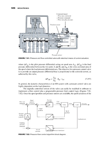
Command signal
---Flow rate command
---Pressure command
---Flow rate plus pressure
Position sensor
DSP,
Amp
Pressure sensor
FIGURE 7.81: Pressure and flow controlled valve with electrical means of control actuation.
where ΔP 12 is the pilot pressure differential acting on spool area A , ΔP AB is the load
12
pressure differential between the two ports A and B, and A is the cross-sectional area of
fb
the spool where the load pressure differential acts. The objective for a pressure control valve
is to provide an output pressure differential that is proportional to the solenoid current, as
achieved by this valve,
A 12
ΔP = ⋅ K ⋅ i (7.257)
AB pi sol
A
fb
In general, the dynamic characteristics of an EH system with a pressure control valve are
highly dependent on the load dynamics.
The digitally controlled version of the valve can easily be modified in software to
implement a flow control plus a programable pressure limit control logic (Figures 7.81,
7.82). Once the spool position and pressure sensors are available, the spool actuation of the
Spool Position
Flow rate position controller Coil
command + command + current Flow Velocity
_ _ X Valve Load
Actual
position
Spool
position
Pressure
limiting
controller u
P
X Position transducer
Load pressure
Limiting
pressure
command _
+
Actual
pressure Pressure transducer
FIGURE 7.82: Pressure-flow control algorithm block diagram.