
Page 515 - Mechatronics with Experiments
P. 515
October 9, 2014 8:41 254mm×178mm
Printer: Yet to Come
JWST499-c07
JWST499-Cetinkunt
ELECTROHYDRAULIC MOTION CONTROL SYSTEMS 501
pump and increase system fault tolerance against the control timing errors between valve
and pump.
The output flow, Q, from a valve is a function of orifice area (A valve ) and pressure
differential across the port (ΔP valve ). The orifice area is a function of the spool displacement
(x spool ) and the geometric design of the spool–orifice geometry. The spool displacement is
proportional to the solenoid current (i ). Hence,
sol
Q = Q(A valve , ΔP valve ) (7.243)
where,
A = A (x ) (7.244)
valve valve spool
x = K ⋅ i (7.245)
spool ix sol
Let us consider a proportional valve, with a flow rating of Q at maximum current, i max ,
nl
and no-load conditions (all of the supply pressure is dropped across the valve). Then the
flow rate at any pressure drop (ΔP valve ) and solenoid current (i ) can be expressed as
sol
(Figure 7.75 and 7.103a type valve)
√
Q∕Q = (i ∕i max ) ΔP valve ∕P s (7.246)
sol
nl
√
= (i ∕i max ) 1 − (ΔP ∕P ) (7.247)
sol
l
s
where the pressure drop across the valve is difference between the pump and tank pressure
(net supply pressure) minus the load pressure (Figure 7.75),
ΔP = P − P −ΔP (7.248)
valve s t l
= P − P −∣ P − P ∣ (7.249)
B
A
s
t
= (P − P ) + (P − P ) or (7.250)
t
B
A
s
= (P − P ) + (P − P ) (7.251)
A
B
s
t
DC P.S.
Control voltage
Amp
P
A
P Q
S O
P A
P
L
T B
P
B
P
T
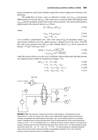
FIGURE 7.75: Test setup for measuring the flow, load pressure, and solenoid current
relationship. In order to measure the flow-current relationship (approximate performance
number to represent this relationship is flow gain, K ), set the load pressure to a standard
p
value. A standard way of measuring the flow-current relationship for servo and proportional
T
valves is: set P s − P to a standard value (i.e., 1000 psi for servo valves, 150 psi for proportional
valves), connect port A to port B directly (hydraulic short circuit, ΔP L = 0), hence pressure drop
= P − P −ΔP = P − P .If P − P cannot be set to a standard desired
across the valve ΔP v s T l s T s T
value, then connect port A and port B with an adjustable restriction (ΔP l ≠ 0) so that the
pressure drop across the valve is a standard value.