
Page 514 - Mechatronics with Experiments
P. 514
JWST499-Cetinkunt
JWST499-c07
500 MECHATRONICS Printer: Yet to Come October 9, 2014 8:41 254mm×178mm
DC P.S.
Control voltage
Amp
P P
S
A
P A
P = P – P B
A
L
B
P P
T B
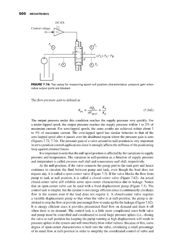
FIGURE 7.74: Test setup for measuring spool null position characteristics: pressure gain when
valve output ports are blocked.
The flow-pressure gain is defined as
Q L K q
K pq = = (7.242)
P spool K p
The output pressure under this condition reaches the supply pressure very quickly. For
a under-lapped spool, the output pressure reaches the supply pressure within 1 to 2% of
maximum current. For zero-lapped spools, the same results are achieved within about 3
to 4% of maximum current. The over-lapped spool has similar behavior to that of the
zero-lapped spool after it passes over the deadband region where the pressure gain is zero
(Figures 7.72, 7.74). The pressure gain of a valve around its null-position is very important
in servo position control applications since it strongly affects the stiffness of the positioning
loop against external forces.
It is important to note that the null spool position is affected by the variations in supply
pressure and temperature. The variation in null-position as a function of supply pressure
and temperature is called pressure null shift and temperature null shift, respectively.
At the null-position, if the valve connects the pump port to the tank port and hence
continues to circulate the fluid between pump and tank, even though the load does not
require any, it is called a open-center valve (Figure 7.3). If the valve blocks the flow from
pump to tank at null position, it is called a closed-center valve (Figure 7.62). An actual
closed-center valve still exhibits some open-center characteristics due to leakage. Notice
that an open-center valve can be used with a fixed displacement pump (Figure 7.3). The
control task is simpler, but the system is not energy efficient since it continuously circulates
flow in the system even if the load does not require it. A closed-center valve requires
a variable displacement pump so that when the valve is at null-position, the pump is de-
stroked to stop the flow or provide just enough flow to make up for the leakage (Figure 7.62).
It is energy efficient since it provides pressurized fluid flow on demand and shuts it off
when there is no demand. The control task is a little more complicated since both valve
and pump must be controlled and coordinated to avoid large pressure spikes (i.e., closing
the valve to null-position but keeping the pump running at high displacement will result in
pressure spikes in the system and will most likely blow relief valves). Because of this, some
degree of open-center characteristics is built into the valve, circulating a small percentage
of its rated flow at null-position in order to simplifiy the coordinated control of valve and