Page 517 - Mechatronics with Experiments
P. 517

Printer: Yet to Come
                                                                                     October 9, 2014 8:41 254mm×178mm
                        JWST499-Cetinkunt
            JWST499-c07
                                                            ELECTROHYDRAULIC MOTION CONTROL SYSTEMS  503
                                               Flow (Q)  dP - constant
                                                        v


                                    Hysteresis


                                                                Current (i)
                                   Deadband          Deadband

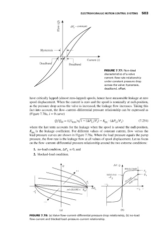
                                                                           FIGURE 7.77: Non-ideal
                                                                           characteristics of a valve
                                                                           current–flow rate relationship
                                                                           under constant pressure drop
                                                                           across the valve: hysteresis,
                                                                           deadband, offset.

                             have critically lapped (almost zero-lapped) spools, hence have measurable leakage at zero
                             spool displacement. When the current is zero and the spool is nominally at null-position,
                             as the pressure drop across the valve is increased, the leakage flow increases. Taking this
                             fact into account, the flow–current–differential pressure relationship can be expressed as
                             (Figure 7.78a, i = 0 curve)
                                                          √
                                             Q∕Q = (i∕i   ) 1 − (ΔP ∕P ) − K  ⋅ (ΔP ∕P )       (7.254)
                                                nl     max         L  s    pq    L   s
                             where the last term accounts for the leakage when the spool is around the null-position,
                             K pq  is the leakage coefficient. For different values of constant current, flow versus the
                             load pressure curves are shown in Figure 7.78a. When the load pressure equals the pump
                             pressure, the flow rate is the leakage flow at all values of spool displacement. Let us focus
                             on the flow–current–differential pressure relationship around the two extreme conditions:

                                1. no-load condition, ΔP = 0, and
                                                    L
                                2. blocked-load condition.


                                                 Q                               P, Q
                                                                                       (Blocked load)
                                                x        + i                                      P
                                                                                                   s
                                                                            Initial slope         Q  r
                                                x
                                                                             =K
                                                                               p
                                                x               P                      (No load)  =K q
                                                                s                         Slope
                                                                           – i r
                                 x x            x             x  x  x
                                                                    P                         + i  i
                                                    i=0 (SLOPE =    K )  L                      r
                                –P              x             pq
                                 s
                                                x
                                      – i       x
                                               (a)                                  (b)
                             FIGURE 7.78: (a) Valve flow–current–differential pressure drop relationship, (b) no-load
                             flow-current and blocked load–pressure–current relationship.
   512   513   514   515   516   517   518   519   520   521   522