
Page 519 - Mechatronics with Experiments
P. 519
Printer: Yet to Come
October 9, 2014 8:41 254mm×178mm
JWST499-c07
JWST499-Cetinkunt
ELECTROHYDRAULIC MOTION CONTROL SYSTEMS 505
motor, or linear force motor) current and the main spool displacement is determined by
two factors:
1. the bandwidth of the electric actuator,
2. the bandwidth of the pilot amplification stage (in direct drive valves, there is no pilot
stage).
For a given valve, as the pilot stage supply pressure increases, the bandwidth of this stage
also increases slightly.
The pilot stage may be supplied either by an external pilot pump or derived internally
from main line pressure. When the pilot supply is derived internally from the main line, the
flow goes through a pressure reducing valve in order to regulate a constant pilot pressure
supply so that the pilot pressure does not fluctuate with the supply pressure (i.e., if the main
pressure supply is a load sensing pump, as the load varies, the main supply pressure varies).
The pilot supply would vary by a small amount as the supply pressure varies. However, if
the modulating bandwidth of the pressure reducing valve is much higher than the main valve
and the actuator, the transient effect of such variation in the pilot pressure is insignificant.
For instance, when the pilot pressure is derived from a main line pump which is controlled
using load sensing feedback, the lowest stand-by pressure setting of the pump should be
above a certain minimum value to make sure the pilot supply is properly maintained.
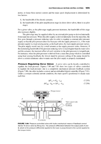
Pressure Regulating Servo Valves A servo valve can be locally controlled to
regulate the load pressure. Figures 7.80 and 7.81 show two types of valves controlled
to regulate the load pressure: one is a completely mechanical pressure feedback system
(Figure 7.80), the other includes a sensor and an embedded digital controller (Figure 7.81).
Under a constant solenoid current condition, the main spool is positioned in steady-state
such that
ΔP 12 = K ⋅ i sol (7.255)
pi
ΔP ⋅ A =ΔP ⋅ A (7.256)
AB fb 12 12
Torque motor
N N
N S
S S
P P
Valve spool with
A A
12 P P 12 pressure
A R feedback
fb
A fb
A B
To actuator
FIGURE 7.80: Pressure controlled valve with hydro-mechanical means of feedback control
(Series 15 servo valve by Moog Inc). The pressure differential between the output ports A and
B, which is the pressure differential applied to the load, is proportional to the current applied to
the torque motor.