
Page 812 - Mechatronics with Experiments
P. 812
798 MECHATRONICS
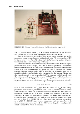
FIGURE 11.32: Picture of the complete circuit for the DC motor control experiment.
where i cmd (t) is the desired current, i mea (t) is the actual (measured) current, K is the current
loop gain, PWM is the output signal value (duty cycle) of the PWM channel.
In order to implement such a closed loop current control algorithm, we need to
measure the current through the motor and interface it to the PIC microcontroller’s ADC
input channel (one of the channels), and sample it at a high sampling rate (i.e., at least ten
times faster than the desired current loop bandwidth).
The motor current is measured by inserting a precision resistor at the bottom leg and
ground connection of the H-bridge (C and GND on the H-bridge circuit). The key here is
that the resistor value should be accurate and stable (not changing much due to temperature)
so that current times the resistor gives us a voltage which we can sample through the ADC
converter. Since the motor amplifier is PWM controlled, the measured voltage may be
passed through a low pass filter before being interfaced to the ADC converter. The low pass
filter bandwidth should be low compared to the PWM frequency, but high enough not to
filter out the current loop dynamics. For instance, if PWM frequency is 10 kHz, and current
loop bandwidth desired is 100 Hz, we can pick a low pass filter with cross-over frequency of
500 Hz or 1000 Hz. The motor current and voltage across the precision resistor is related as
V (t) = R ⋅ i (t) (11.131)
mea s mea
where R is the precision resistor, i (t) is the motor current, and V (t) is the voltage
s mea mea
proportional to the current. R should be as small a value as possible in order to not add
s
additional resistance to the circuit for the purpose of current measurement. Since the current
measurement resistor acts as a series resistor with the motor resistance, it should not be
significantly increasing the total resistance. Relative to the motor winding resistance, R ,
m
R should be in the range of 1∕1000 ⋅ R . For instance, in an application where R = 10 Ω,
s
m
m
i = i max = 10 A, V = 100 VDC DC bus voltage supply, the maximum power of the
ss
m
motor is 1000 W = 1 kW. If we use a current measurement precision resistor R = 0.1 Ω,
s
2
at maximum current, there would be R ⋅ i = 10 W power dissipation (wasted power) in
s
order to accomplish the current measurement.