
Page 814 - Mechatronics with Experiments
P. 814
800 MECHATRONICS
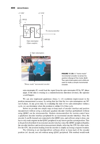
+5 VDC +5 VDC
100 Ω
+
+
E To microcontroller
100 kΩ
Opto interruptor
(Opto coupler)
2 Opto-interrupters
FIGURE 11.33: A “home-made”
incremental encoder to sense the
position change of the motor shaft.
Two opto-interrupters and a disk are
used to make a simple incremental
"Home-made" incremental encoder encoder.
◦
opto-interrupter #1 would lead the signal from the opto-interrupter #2 by 90 phase
angle. If the disk is rotating in a counterclockwise direction (reverse), the opposite
would happen.
We can also implement quadrature (times 4, ×4) resolution improvement in the
position measurement accuracy by noting that fact that the two opto-interruptors are 90 ◦
out of phase. At any given time, by evaluating the state of two opto-interrupters within a
cycle, we can determine where the position is within 1/4 of that cycle.
Below we provide two simple ways to keep track of encoder interface and position
measurement without using a dedicated quadrate decoder interface perhipheral (without
using QDEC) on the microcontroller. Modern microcontrollers for motion control have
a quadrature decoder interface peripheral for an incremental encoder interface. Once the
encoder A and B channels are connected to the QDEC pins, and software setup is done, one
has to only read a register in the QDEC peripheral at any time to get the current position. This
is the preferred method of incremental encoder interface since the QDEC peripheral handles
the encoder interface and position measurement details, relieving the CPU for other tasks.
For the CPU, the position reading from the encoder is simply accessing a register location.
The following is an interrupt-driven software driver to keep track of the encoder
position (×1 decode, not ×4) without using QDEC peripheral. This method would work