
Page 817 - Mechatronics with Experiments
P. 817
LABORATORY EXPERIMENTS 803
interrupt service routine, we would determine the direction of the motion and increment or
decrement the position count.
In microcontrollers with a dedicated incremental encoder interface (also called a
quadrature decoder circuit), the microcontroller does not have to service the interface for
each pulse. Rather, at any given time it would read the counter register since the interface
circuit handles the counting process. PIC microcontroller 18F4431 has one incremental
encoder interface (Figure 11.34). As a result, implementing this experiment with PIC
18F4331 is much easier than with PIC 18F452. The interface is capable of decoding
the incremental position information with ×4 multiplication, as a result, it is commonly
referred to as the “quadrature decoder” or QDEC interface. The pin numbers RA2, RA3,
RA4 are programmable to interface to the INDEX, channel A, and channel B of the encoder,
respectively. In our experiment, we do not use the INDEX signal. PWM output channels
can be assigned to pin RB0 for PWM channel 1, and pin RB1 for PWM channel 2. We
can then use PWM channel 1 to control one pair of the transistors of the H-bridge, and the
PWM channel 2 to control the other pair of the transistors of the H-bridge.
Once we know the actual position, we can digitally calculate the actual (estimated)
speed of the shaft. Then, if we have a programmed (desired) position or velocity, we can
determine the PWM output based on a PID type control algorithm, that is PD algorithms
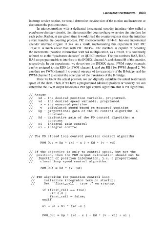
// Assume
// xd - the desired position variable, programmed.
// vd - the desired speed variable, programmed.
// x - the measured position
// v - calculated speed based on measured position
// Kp - proportional gain of the PD control algorithm: a
constant.
// Kd - derivative gain of the PD control algorithm: a
constant
// Ki - integral gain control
// ui - integral control
// The PD closed loop control position control algorithm
PWM_Out = Kp * (xd - x ) + Kd * (v - vd)
// If the objective is only to control speed, but not the
// position, then the PWM output calculation should not be
// function of position information, i.e. a proportional
// closed loop speed control algorithm.
PWM_Out = Kd * (v -vd)
// PID algorithm for position control loop
// Initialize integrator term on startup;
// Set “first_call = true ;” on startup.
if (first_call == true)
ui= 0.0 ;
first_call = false;
endif
ui = ui + Ki * (xd -x )
PWM_Out = Kp *(xd-x)+Kd*(v-vd)+ui;