Page 815 - Mechatronics with Experiments
P. 815
LABORATORY EXPERIMENTS  801
                             only at relatively low speeds of motor, that is the speed of the motor is so low that the
                             time period between each pulse of the encoder is long enough for the microcontroller
                             to have sufficient time to handle each pulse as an interrupt, execute the ISR (Interrupt
                             Service Routine) routine to keep track of position count, and also perform other logic
                             functions.
                                1. Hardware interface: Encoder channel A is connected to a digital input pin, Encoder
                                  channel B is connected to another digital input pin of the microcontroller.
                                2. Software driver:
                                  (a) Software setup: Digital input pin connected to Encoder channel A is setup to
                                     generate interrupt on rising-edge. Initially, the position count is set to zero. An
                                     ISR is setup for the interrupt handling.
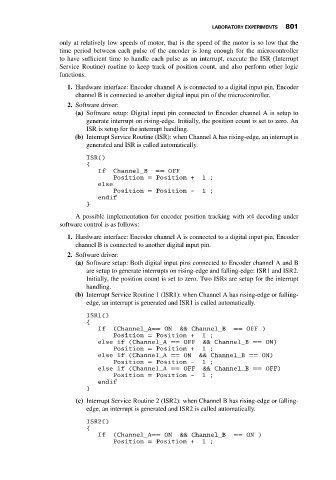
                                  (b) Interrupt Service Routine (ISR): when Channel A has rising-edge, an interrupt is
                                     generated and ISR is called automatically.

                                     ISR()
                                     {
                                         If   Channel_B   == OFF
                                             Position = Position +      1 ;
                                         else
                                             Position = Position -      1 ;
                                         endif
                                     }

                                  A possible implementation for encoder position tracking with ×4 decoding under
                             software control is as follows:

                                1. Hardware interface: Encoder channel A is connected to a digital input pin, Encoder
                                  channel B is connected to another digital input pin.
                                2. Software driver:
                                  (a) Software setup: Both digital input pins connected to Encoder channel A and B
                                     are setup to generate interrupts on rising-edge and falling-edge: ISR1 and ISR2.
                                     Initially, the position count is set to zero. Two ISRs are setup for the interrupt
                                     handling.
                                  (b) Interrupt Service Routine 1 (ISR1): when Channel A has rising-edge or falling-
                                     edge, an interrupt is generated and ISR1 is called automatically.
                                     ISR1()
                                     {
                                         If   (Channel_A== ON     && Channel_B    == OFF )
                                             Position = Position +      1 ;
                                         else if (Channel_A == OFF      && Channel_B == ON)
                                              Position = Position +     1 ;
                                         else if (Channel_A == ON      && Channel_B == ON)
                                             Position = Position -      1 ;
                                         else if (Channel_A == OFF      && Channel_B == OFF)
                                              Position = Position -     1 ;
                                         endif
                                     }
                                  (c) Interrupt Service Routine 2 (ISR2): when Channel B has rising-edge or falling-
                                     edge, an interrupt is generated and ISR2 is called automatically.
                                     ISR2()
                                     {
                                         If   (Channel_A== ON     && Channel_B    == ON )
                                             Position = Position +      1 ;

