
Page 818 - Mechatronics with Experiments
P. 818
804 MECHATRONICS
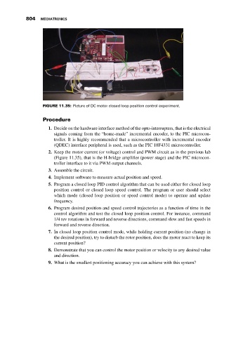
FIGURE 11.35: Picture of DC motor closed loop position control experiment.
Procedure
1. Decide on the hardware interface method of the opto-interrupters, that is the electrical
signals coming from the “home-made” incremental encoder, to the PIC microcon-
troller. It is highly recommended that a microcontroller with incremental encoder
(QDEC) interface peripheral is used, such as the PIC 18F4331 microcontroller.
2. Keep the motor current (or voltage) control and PWM circuit as in the previous lab
(Figure 11.35), that is the H-bridge amplifier (power stage) and the PIC microcon-
troller interface to it via PWM output channels.
3. Assemble the circuit.
4. Implement software to measure actual position and speed.
5. Program a closed loop PID control algorithm that can be used either for closed loop
position control or closed loop speed control. The program or user should select
which mode (closed loop position or speed control mode) to operate and update
frequency.
6. Program desired position and speed control trajectories as a function of time in the
control algorithm and test the closed loop position control. For instance, command
1/4 rev rotations in forward and reverse directions, command slow and fast speeds in
forward and reverse direction.
7. In closed loop position control mode, while holding current position (no change in
the desired position), try to disturb the rotor position, does the motor react to keep its
current position?
8. Demonstrate that you can control the motor position or velocity to any desired value
and direction.
9. What is the smallest positioning accuracy you can achieve with this system?