Page 816 - Mechatronics with Experiments
P. 816

802   MECHATRONICS
                                         else if (Channel_A == OFF       && Channel_B == OFF)
                                              Position = Position +      1 ;
                                         else if (Channel_A == ON       && Channel_B == OFF)
                                              Position = Position -      1 ;
                                         else if (Channel_A == OFF       && Channel_B == ON)
                                              Position = Position -      1 ;
                                         endif
                                      }


                              Application Software Description
                              In most microcontrollers for motion control applications, there is a dedicated chip to
                              interface to the encoder and count the position change pulses as well as calculate the speed.
                              However, in the PIC 18F452 microcontroller we have used so far, such a peripheral is not
                              available, whereas PIC 18F4431 does have an incremental encoder interface peripheral. For
                              PIC 18F452, we can implement the incremental encoder interface using discrete input lines.
                              We can either connect the two opto-interrupter signals to two digital inputs and sample them
                              fast enough so that we do not lose any pulse, or we can connect them to hardware interrupt
                              lines. In the latter case, everytime a pulse transition occurs, an interrupt is generated. At the


                                                                9 V

                                                                                     9 V
                                                              1 kΩ
                               PWM 0 O/P
                              PORT B, Pin 0  1 kΩ
                              Opto#2 I/P
                           QEA, PORT A, Pin 3
                                                                                 IN4003  IN4003
                            PIC 18F4331


                                                              1 kΩ
                               PWM 1 O/P                                            Encoder
                              PORT B, Pin 1  1 kΩ
                                                                                 IN4003
                                Opto#1 I/P                                             IN4003
                           QEB, PORT A, Pin 4


                                                                                Opto #1 signal  Opto #2 signal
                                              Optointerrupter
                                                                   + 5 V    + 5 V    + 5 V   + 5 V
                                                 circuit
                                                                 100 Ω            100 Ω
                                                                     +                +
                                                                            +                +
                                                                              To Microcontroller  To Microcontroller
                                                                            D                D
                                                                     E                E
                                                                             100 kΩ            100 kΩ
                                     90 degrees phase shift
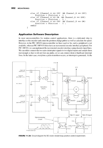
                              FIGURE 11.34: Circuit diagram for DC motor closed loop position control experiment.
   811   812   813   814   815   816   817   818   819   820   821