
Page 192 - Servo Motors and Industrial Control Theory -
P. 192
Appendix B 189
9. Repeat problem 8 when the required position of the roots of characteristic equa-
tion must be set to have the same value as,
ss ss,, , 4 :=−50
3
2
1
It means that all roots must have a time constant of 0.02 s. The gains of the
feedback signals for this problem will be different from the previous problem.
Note that for both problems you need to expand the determinant of the dynamic
matrix symbolically.
10. Solve both problems of 8 and 9 by numerical integration technique and com-
pare the transient response for step input of xi. You should observe that both
responses have a dominant time constant of 0.02 s and the remaining roots only
affect the transient response behavior. Discuss the differences and make some
conclusions.
11. In problem 8, obtain the steady state error for step input of xil. You should
notice that there is a large steady state error. Add an integrator after the control-
ler and before the position where the force is generated. Obviously, the order of
state equation increases to five and you should now obtain five gains for state
variables so the all rootsmove to the following over damped positions,
s :=−50
1
s :=−75
2
s :=−100
3
s :=−160
4
s :=−200
5
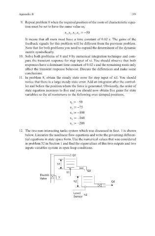
12. The two non-interacting tanks system which was discussed in Sect. 1 is shown
below. Linearize the nonlinear flow equations and write the governing differen-
tial equations in state space form. Use the numerical values that was considered
in problem 52 in Section 1 and find the eigenvalues of this two outputs and two
inputs variables system in open loop conditions.
Q1
h1
Q2
h1
Electric
Valve Y
h2 Q0
Level h2
Sensor