
Page 197 - Servo Motors and Industrial Control Theory -
P. 197
194 Appendix B
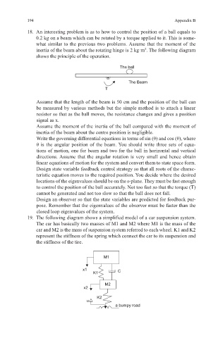
18. An interesting problem is as to how to control the position of a ball equals to
0.2 kg on a beam which can be rotated by a torque applied to it. This is some-
what similar to the previous two problems. Assume that the moment of the
inertia of the beam about the rotating hinge is 2 kg·m . The following diagram
2
shows the principle of the operation.
The ball
The Beam
T
Assume that the length of the beam is 50 cm and the position of the ball can
be measured by various methods but the simple method is to attach a linear
resistor so that as the ball moves, the resistance changes and gives a position
signal as x.
Assume the moment of the inertia of the ball compared with the moment of
inertia of the beam about the centre position is negligible.
Write the governing differential equations in terms of sin (θ) and cos (θ), where
θ is the angular position of the beam. You should write three sets of equa-
tions of motion, one for beam and two for the ball in horizontal and vertical
directions. Assume that the angular rotation is very small and hence obtain
linear equations of motion for the system and convert them to state space form.
Design state variable feedback control strategy so that all roots of the charac-
teristic equation moves to the required position. You decide where the desired
locations of the eigenvalues should be on the s-plane. They must be fast enough
to control the position of the ball accurately. Not too fast so that the torque (T)
cannot be generated and not too slow so that the ball does not fall.
Design an observer so that the state variables are predicted for feedback pur-
pose. Remember that the eigenvalues of the observer must be faster than the
closed loop eigenvalues of the system.
19. The following diagram shows a simplified model of a car suspension system.
The car has basically two masses of M1 and M2 where M1 is the mass of the
car and M2 is the mass of suspension system referred to each wheel. K1 and K2
represent the stiffness of the spring which connect the car to its suspension and
the stiffness of the tire.
M1
x1 C
K1
M2
x2
K2
u
a bumpy road