
Page 200 - Servo Motors and Industrial Control Theory -
P. 200
Appendix B 197
system e. You should define three state variables for the open loop transfer
function and this is straightforward. Then, write the error equation which is,
e: θ − θ and then modify the state equation to include this equation. Now, the
i
o
state equation has three state variables and one output variable. The above pro-
cedure avoids the complicated calculation of the closed loop transfer function.
Change the value of the gain K and derive the eigenvalues of the system. You
should choose the maximum values of the gain to minimize the steady state
error and make sure that the system remains stable with sufficient damping in
the dominant root(s).
You should note that the above system represents quite a fast response char-
acteristic for mechanical system and it may not be as fast as when electronics
are involved.
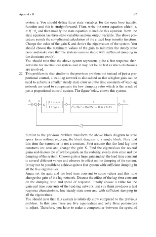
22. This problem is also similar to the previous problem but instead of just a pro-
portional control, a lead-lag network is also added so that a higher gain can be
used to achieve a smaller steady state error and the time constants of lead-lag
network are used to compensate for low damping ratio which is the result of
just a proportional control system. The figure below shows this system.
θ i e (1 + τ • s) 1 θ o
K 1
4
1 + τ • s s + 21s + 524.25s + 585s + 2125
2
3
2
Similar to the previous problem transform the above block diagram to state
space form without reducing the block diagram to a single block. Note that
this time the numerator is not a constant. First assume that the lead-lag time
constants are zero and change the gain K. Find the eigenvalues for several
gains and discuss the effect the gain K on the stability, steady state error and the
damping of the system. Choose quite a large gain and set the lead time constant
to several different values and observe its effect on the damping of the system.
It may not be possible to achieve quite a fast system with sufficient damping in
all the five eigenvalues.
Again set the gain and the lead time constant to some values and this time
change the gain of the lag network. Discuss the effect of the lag time constant
on the damping ratio and speed of response. Finally choose a value for the
gain and time constants of the lead-lag network that you think produces a fast
response characteristic, low steady state error and with sufficient damping in
all the eigenvalues.
You should note that this system is relatively slow compared to the previous
problem. In this case there are five eigenvalues and only three parameters
to adjust. Therefore, you have to make a compromise between the speed of