
Page 201 - Servo Motors and Industrial Control Theory -
P. 201
198 Appendix B
response, steady state error and the acceptable damping ratio in the system.
You should make few of the eigenvalues to dominate the response which means
these eigenvalues must be close to the origin of s-plane. The eigenvalues which
are further away from the origin must be stable but low damping ratios are ac-
ceptable because they decay quite rapidly.
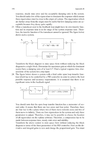
23. Often a transducer used in the feedback loop might have its own transfer func-
tion and its response time is in the range of the system response time. There-
fore, the transfer function of the transducer cannot be ignored. The figure below
shows such a system.
θ i e θ o
+ K
-
2
3
s + 16s + 68s + 80
1
0.8s + 1
Transform the block diagram to state space form without reducing the block
diagram to a single block. Determine the maximum gain at which the dominant
root(s) have a damping ratio of at least 0.7. Find a typical response time char-
acteristic of the system for a step input.
24. The figure below shows a system with a third order open loop transfer func-
tion which has to be controlled by a PID controller in order to achieve the best
possible response and accuracy requirements. It is assumed that there is no
significant noise in the feedback signal.
y i e K 1 Yo
+ K + i •s
- p s + k d s + 120s + 14500s +250000
2
3
You should note that the open loop transfer function has a numerator of sec-
ond order. It means that there are two zeros and four poles. Therefore, there
are four loci in the s-plane where two of them move towards zeros and two of
them move to infinity. There are four eigenvalues in the system and only three
parameters to adjust. Therefore, it may not be possible to choose the location
of all eigenvalues on the s-plane arbitrary. Therefore, a compromise has to be
made between response time, steady state error and stability.
Transform the above system to state space form without reducing the block
diagram in terms of the three parameters of the PID controller. First set the de-
rivative and integral gains to zero and change the proportional gain. You must