
Page 206 - Servo Motors and Industrial Control Theory -
P. 206
Appendix B 203
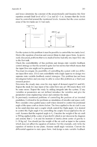
and hence determine the constant of the proportionally and linearize this flow
equation around fluid level of h1 = 2 m and h2 = 1 m. Assume that the levels
must be controlled around the mentioned levels. Assume that the cross section
areas of the two tanks are 1.5 m2 each.
q1
q2
h1 h2
q0
For the system in this problem it must be possible to control the two tanks level.
Derive the equation of motion and convert them to state space form. As previ-
ously discussed, problems that were studied before had only one input flow rate
to the first tank.
Check the controllability of this problem and design state variable feedback
control strategy so that the system is quite fast but not too fast which means that
the input flow rate might not be generated.
You must investigate the possibility of controlling the system with two differ-
ent input flow rates. If it is not controllable with single input try to design two
separate state variable feedback control strategies. This problem has not been
investigated before and you may be able to select this problem as a final year
research project.
Determine the steady state error for step input of demand signal h1i and h2i.
Repeat the study for step input of the outlet flow rate q0. Obviously there will
be some errors. Repeat the study by adding integrals into the system. If any
variables or parameters are not defined introduce the variables and give the
parameters some engineering values and continue the study.
32. In previously mentioned problems of controlling the position of an inverted
pendulum, I referred to the problems as simulation of missiles and space craft.
Now consider a true guided space craft where desired to control the positional
angle of the space craft as shown below. The force applied to the air craft is one
in the axial direction and a couple which control the flight angle. It is desired
to control the flight angle θ by controlling the couple forced applied to the air
craft. Assume that the required angle is θ . Consider the weight of the air craft
i
is 500 kg applied at the center of gravity(G) which is not shown in the diagram
and assume that L = 2 m and the moment of inertia about center of gravity is
I = 50 kg·m2. You should put the weight of the air craft as input to the system
which does not affect the equation of motion. For this example, only write the
equation of motion in one plane. Assume small angle variation. Convert the
differential equation to state space form. And design a state variable feedback