
Page 211 - Servo Motors and Industrial Control Theory -
P. 211
Appendix C 209
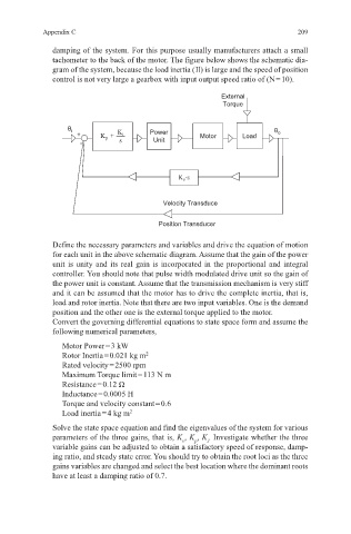
damping of the system. For this purpose usually manufacturers attach a small
tachometer to the back of the motor. The figure below shows the schematic dia-
gram of the system, because the load inertia ( Il) is large and the speed of position
control is not very large a gearbox with input output speed ratio of (N = 10).
External
Torque
θ i Power θ o
+ K + K i Motor Load
p
- s Unit
K v ·s
Velocity Transduce
Position Transducer
Define the necessary parameters and variables and drive the equation of motion
for each unit in the above schematic diagram. Assume that the gain of the power
unit is unity and its real gain is incorporated in the proportional and integral
controller. You should note that pulse width modulated drive unit so the gain of
the power unit is constant. Assume that the transmission mechanism is very stiff
and it can be assumed that the motor has to drive the complete inertia, that is,
load and rotor inertia. Note that there are two input variables. One is the demand
position and the other one is the external torque applied to the motor.
Convert the governing differential equations to state space form and assume the
following numerical parameters,
Motor Power = 3 kW
Rotor Inertia = 0.021 kg m 2
Rated velocity = 2500 rpm
Maximum Torque limit = 113 N m
Resistance = 0.12 Ω
Inductance = 0.0005 H
Torque and velocity constant = 0.6
Load inertia = 4 kg m 2
Solve the state space equation and find the eigenvalues of the system for various
parameters of the three gains, that is, K , K , K . Investigate whether the three
v
i
p
variable gains can be adjusted to obtain a satisfactory speed of response, damp-
ing ratio, and steady state error. You should try to obtain the root loci as the three
gains variables are changed and select the best location where the dominant roots
have at least a damping ratio of 0.7.