
Page 214 - Servo Motors and Industrial Control Theory -
P. 214
212 Appendix C
Determine the gain vector for state variables so that all eigenvalues are moved to
the required position on the s-plane. You decide where the eigenvalues should be
moved so that the fundamental eigenvalues have at least a damping ratio of 0.7
and they are sufficiently away from the origin to give fast response to changes
to the input signals.
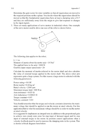
5. There are many applications of servo motors in industrial robots. One example
of the servo motor used to drive one axis of the robot is shown below.
L
Gearbox
F
Motor
The following data applies to the robot;
L = 1 m
Moment of inertia about the motor axis = 10 Nm 2
The applied force to the arm = 1000 N
Gearbox input output speed ratio = 20
Calculate the moment of inertia referred to the motor shaft and also calculate
the value of external torque applied to the motor shaft. The above robot arm
represents quite a large system. For this reason a large motor is selected with the
following parameters.
Power rating = 10 kW
Rotor inertia = 0.24 kg m 2
Rated velocity = 2500 rpm
Maximum torque limit = 800 N m
Arm resistance = 0.025 Ω
Arm inductance = 0.00021 H
Torque constant = 0.83
Velocity constant = 0.83
You should remember that the torque and velocity constants determine the maxi-
mum voltage that should be applied to run the motor at rated velocity. For this
application that is what the maximum voltage should be in order to run the motor
at rated velocity.
It is suggested to implement an integral term in addition to the proportional gain
to achieve zero steady state error for step input of demand signal and for step
input of external torque to the motor. In position control applications often a
velocity feedback must be used to increase the damping ratio in the system. This
is shown in block diagram form below.