
Page 209 - Servo Motors and Industrial Control Theory -
P. 209
Appendix C: Exercise Problems on Servo
Motors (Chaps. 4–9)
C.1 Electrical DC Servo Motors
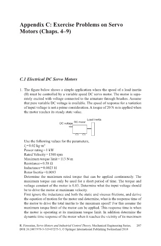
1. The figure below shows a simple application where the speed of a load inertia
(Il) must be controlled by a variable speed DC servo motor. The motor is sepa-
rately excited with voltage connected to the armature through brushes. Assume
that pure variable DC voltage is available. The speed of response for a variation
of input voltage is not a prime consideration. A torque of 20 N m is applied when
the motor reaches its steady state value.
Load Inertia
DC voltage DC motor
Use the following values for the parameters,
I = 0.02 kg·m 2
l
Power rating = 1 kW
Rated Velocity = 1300 rpm
Maximum torque limit = 113 N m
Resistance = 0.58 Ω
Inductance = 0.0023 H
Rotor Inertia = 0.0093
Determine the maximum rated torque that can be applied continuously. The
maximum torque can only be used for a short period of time. The torque and
voltage constant of the motor is 0.83. Determine what the input voltage should
be to drive the motor at maximum velocity.
First ignore the inductance and both the static and viscous frictions, and derive
the equation of motion for the motor and determine, what is the response time of
the motor to drive the total inertia to the maximum speed? For this assume the
maximum torque limit of the motor can be applied. This response time is when
the motor is operating at its maximum torque limit. In addition determine the
dynamic time response of the motor when it reaches the vicinity of its maximum
R. Firoozian, Servo Motors and Industrial Control Theory, Mechanical Engineering Series, 207
DOI 10.1007/978-3-319-07275-3, © Springer International Publishing Switzerland 2014