
Page 217 - Servo Motors and Industrial Control Theory -
P. 217
Appendix C 215
You should note that the amplitude of the voltage for each phase is taken as
220 V and for motors requiring lower voltage. A transformer may be used at the
input side to reduce the voltage to the required value.
You should also note that the gain around zero firing angle is very small and to
overcome this problem the thyristors are fired around 5–6° in both directions to
have reasonable gain at low firing angles.
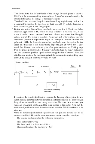
7. Before attempting this problem you should solve problem 6. The figure below
shows an application of DC motor to drive a table of a machine tool. A lead
screw is used to convert rotational motion to a linear movement. For this appli-
cation, a small DC motor is selected. The power unit of three phase thyristor
controlled system which produces output DC voltage in the form of controlled
pulses at 150 Hz. To design the controller you should study the system for two
cases. The first case is that at low firing angle the gain of power unit is quite
small. For this case, determine the gain of the power unit around 5° firing angle
from the previous problem. For this case you should study the steady state errors
due to a command position signal and due to application of external force. For
stability, you must use the maximum gain of the power unit when the firing angle
is 90°. Find this gain from the previous problem.
Demand position
Controller Power unit Table X 0
K i
K p + K 1 Motor
X i s Lead screw
1+ K d s
Position and velocity
feedback
In practice, the velocity feedback to improve the damping of the system is mea-
sured directly from the motor or from the end of lead screw. In the controller, an
integral is used to achieve zero steady state value. Note that there are two input
variables of demand position and the force applied to the motor. Note that the
feedback signal is subtracted from the demand position. This is not shown in the
diagram.
Write the governing differential equations for each part and assume that the in-
ductance and flexibility of the transmission mechanism must be considered.
The loading mechanism has the following parameters,
Mass of the table = 50 kg
The force applied to the table = 1000 N
Maximum length of the lead screw = 2 m