
Page 220 - Servo Motors and Industrial Control Theory -
P. 220
218 Appendix C
the reliability. Brushless DC servo motors usually are more expensive than the
brushed motor and the power unit is more complex. The maximum torque pro-
vided by brushless motors may not be as much as brushed DC motors. The au-
thor has no information on brushless DC servo motors. The reader is encouraged
to obtain some engineering data from the manufacturer of these types of motors.
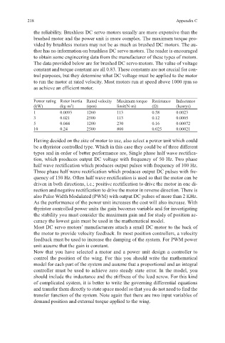
The data provided below are for brushed DC servo motors. The value of voltage
constant and torque constant are all 0.83. These constants are not crucial for con-
trol purposes, but they determine what DC voltage must be applied to the motor
to run the motor at rated velocity. Most motors run at speed above 1000 rpm so
as achieve an efficient motor.
Power rating Rotor inertia Rated velocity Maximum torque Resistance Inductance
(kW) (kg·m ) (rpm) limit(N·m) (Ω) (henrys)
2
1 0.0093 1260 113 0.58 0.0023
3 0.021 2500 113 0.12 0.0005
5 0.044 1200 230 0.16 0.00072
10 0.24 2500 800 0.025 0.00021
Having decided on the size of motor to use, also select a power unit which could
be a thyristor controlled type. Which in this case they could be of three different
types and in order of better performance are, Single phase half wave rectifica-
tion, which produces output DC voltage with frequency of 50 Hz. Two phase
half wave rectification which produces output pulses with frequency of 100 Hz.
Three phase half wave rectification which produces output DC pulses with fre-
quency of 150 Hz. Often half wave rectification is used so that the motor can be
driven in both directions, i.e.; positive rectification to drive the motor in one di-
rection and negative rectification to drive the motor in reverse direction. There is
also Pulse Width Modulated (PWM) with output DC pulses of more than 2 KHz.
As the performance of the power unit increases the cost will also increase. With
thyristor controlled power units the gain becomes variable and for investigating
the stability you must consider the maximum gain and for study of position ac-
curacy the lowest gain must be used in the mathematical model.
Most DC servo motors’ manufacturers attach a small DC motor to the back of
the motor to provide velocity feedback. In most position controllers, a velocity
feedback must be used to increase the damping of the system. For PWM power
unit assume that the gain is constant.
Now that you have selected a motor and a power unit design a controller to
control the position of the wing. For this you should write the mathematical
model for each part of the system and assume that a proportional and an integral
controller must be used to achieve zero steady state error. In the model, you
should include the inductance and the stiffness of the lead screw. For this kind
of complicated system, it is better to write the governing differential equations
and transfer them directly to state space model so that you do not need to find the
transfer function of the system. Note again that there are two input variables of
demand position and external torque applied to the wing.