
Page 223 - Servo Motors and Industrial Control Theory -
P. 223
Appendix C 221
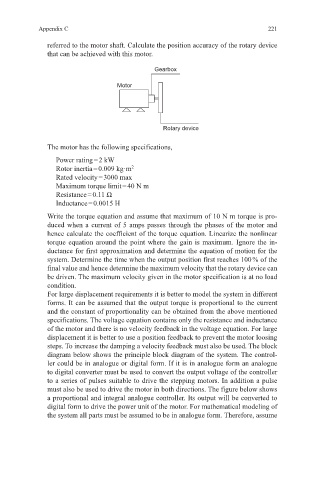
referred to the motor shaft. Calculate the position accuracy of the rotary device
that can be achieved with this motor.
Gearbox
Motor
Rotary device
The motor has the following specifications,
Power rating = 2 kW
Rotor inertia = 0.009 kg·m 2
Rated velocity = 3000 max
Maximum torque limit = 40 N m
Resistance = 0.11 Ω
Inductance = 0.0015 H
Write the torque equation and assume that maximum of 10 N m torque is pro-
duced when a current of 5 amps passes through the phases of the motor and
hence calculate the coefficient of the torque equation. Linearize the nonlinear
torque equation around the point where the gain is maximum. Ignore the in-
ductance for first approximation and determine the equation of motion for the
system. Determine the time when the output position first reaches 100 % of the
final value and hence determine the maximum velocity that the rotary device can
be driven. The maximum velocity given in the motor specification is at no load
condition.
For large displacement requirements it is better to model the system in different
forms. It can be assumed that the output torque is proportional to the current
and the constant of proportionality can be obtained from the above mentioned
specifications. The voltage equation contains only the resistance and inductance
of the motor and there is no velocity feedback in the voltage equation. For large
displacement it is better to use a position feedback to prevent the motor loosing
steps. To increase the damping a velocity feedback must also be used. The block
diagram below shows the principle block diagram of the system. The control-
ler could be in analogue or digital form. If it is in analogue form an analogue
to digital converter must be used to convert the output voltage of the controller
to a series of pulses suitable to drive the stepping motors. In addition a pulse
must also be used to drive the motor in both directions. The figure below shows
a proportional and integral analogue controller. Its output will be converted to
digital form to drive the power unit of the motor. For mathematical modeling of
the system all parts must be assumed to be in analogue form. Therefore, assume