
Page 227 - Servo Motors and Industrial Control Theory -
P. 227
Appendix C 225
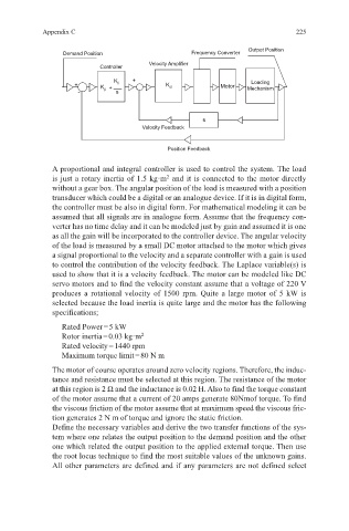
Outpot Position
Demand Position Frequency Converter
Velocity Amplifier
Controller
+ Loading
+ K p + K i - K d Motor Mechanism
- s
s
Velocity Feedback
Position Feedback
A proportional and integral controller is used to control the system. The load
2
is just a rotary inertia of 1.5 kg·m and it is connected to the motor directly
without a gear box. The angular position of the load is measured with a position
transducer which could be a digital or an analogue device. If it is in digital form,
the controller must be also in digital form. For mathematical modeling it can be
assumed that all signals are in analogue form. Assume that the frequency con-
verter has no time delay and it can be modeled just by gain and assumed it is one
as all the gain will be incorporated to the controller device. The angular velocity
of the load is measured by a small DC motor attached to the motor which gives
a signal proportional to the velocity and a separate controller with a gain is used
to control the contribution of the velocity feedback. The Laplace variable(s) is
used to show that it is a velocity feedback. The motor can be modeled like DC
servo motors and to find the velocity constant assume that a voltage of 220 V
produces a rotational velocity of 1500 rpm. Quite a large motor of 5 kW is
selected because the load inertia is quite large and the motor has the following
specifications;
Rated Power = 5 kW
Rotor inertia = 0.03 kg·m 2
Rated velocity = 1440 rpm
Maximum torque limit = 80 N m
The motor of course operates around zero velocity regions. Therefore, the induc-
tance and resistance must be selected at this region. The resistance of the motor
at this region is 2 Ω and the inductance is 0.02 H. Also to find the torque constant
of the motor assume that a current of 20 amps generate 80Nmof torque. To find
the viscous friction of the motor assume that at maximum speed the viscous fric-
tion generates 2 N m of torque and ignore the static friction.
Define the necessary variables and derive the two transfer functions of the sys-
tem where one relates the output position to the demand position and the other
one which related the output position to the applied external torque. Then use
the root locus technique to find the most suitable values of the unknown gains.
All other parameters are defined and if any parameters are not defined select