
Page 231 - Servo Motors and Industrial Control Theory -
P. 231
Appendix C 229
this question assume engineering values for them and using the root locus tech-
nique find the most suitable values of the controller gain which gives maximum
speed of response with sufficient damping in the system and minimum steady
state error.
To improve the performance an integral in addition to proportional control may
be added to the controller. The velocity feedback may also be used to increase
the damping of the system. In this case there are three gains to be adjusted. Again
use the root locus technique to find the three optimized gains of the controller
and the gain of the velocity feedback. Note that the aim is to reduce the dynamic
response time to reduce the steady state error at the same time there must be
sufficient damping in the system to have an acceptable dynamic response char-
acteristic.
Convert the transfer function to state space form and then using numerical in-
tegration technique determine the dynamic position drop when an external of
external torque of 5 (N·m) is suddenly applied. Discuss the acceptability of this
error and discuss how this error might be reduced.
C.5 Actuators based on Electro-Rheological Fluid (ERF)
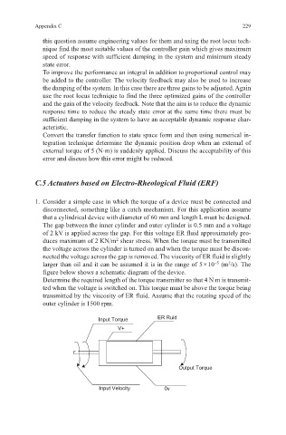
1. Consider a simple case in which the torque of a device must be connected and
disconnected, something like a catch mechanism. For this application assume
that a cylindrical device with diameter of 60 mm and length L must be designed.
The gap between the inner cylinder and outer cylinder is 0.5 mm and a voltage
of 2 kV is applied across the gap. For this voltage ER fluid approximately pro-
2
duces maximum of 2 KN/m shear stress. When the torque must be transmitted
the voltage across the cylinder is turned on and when the torque must be discon-
nected the voltage across the gap is removed. The viscosity of ER fluid is slightly
2
−5
larger than oil and it can be assumed it is in the range of 5 × 10 (m /s). The
figure below shows a schematic diagram of the device.
Determine the required length of the torque transmitter so that 4 N m is transmit-
ted when the voltage is switched on. This torque must be above the torque being
transmitted by the viscosity of ER fluid. Assume that the rotating speed of the
outer cylinder is 1500 rpm.
Input Torque ER Ruid
V+
Output Torque
Input Velocity 0v