
Page 230 - Servo Motors and Industrial Control Theory -
P. 230
228 Appendix C
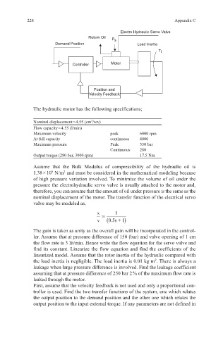
Electro Hydraulic Servo Valve
Return Oil
P s
Demand Position Load Inertia
T l
Controller Motor
Position and
Velocity Feedback
The hydraulic motor has the following specifications;
Nominal displacement = 4.55 (cm /rev)
3
Flow capacity = 4.55 (l/min)
Maximum velocity peak 6000 rpm
At full capacity continuous 4000
Maximum pressure Peak 350 bar
Continuous 280
Output torque (280 bar, 3000 rpm) 17.5 Nm
Assume that the Bulk Modulus of compressibility of the hydraulic oil is
1.38 × 10 N/m and must be considered in the mathematical modeling because
2
9
of high pressure variation involved. To minimize the volume of oil under the
pressure the electrohydraulic servo valve is usually attached to the motor and,
therefore, you can assume that the amount of oil under pressure is the same as the
nominal displacement of the motor. The transfer function of the electrical servo
valve may be modeled as,
x := 1
v . (05 s + 1)
The gain is taken as unity as the overall gain will be incorporated in the control-
ler. Assume that at pressure difference of 150 (bar) and valve opening of 1 cm
the flow rate is 3 lit/min. Hence write the flow equation for the servo valve and
find its constant. Linearize the flow equation and find the coefficients of the
linearized model. Assume that the rotor inertia of the hydraulic compared with
2
the load inertia is negligible. The load inertia is 0.01 kg·m . There is always a
leakage when large pressure difference is involved. Find the leakage coefficient
assuming that at pressure difference of 250 bar 2 % of the maximum flow rate is
leaked through the motor.
First, assume that the velocity feedback is not used and only a proportional con-
troller is used. Find the two transfer functions of the system, one which relates
the output position to the demand position and the other one which relates the
output position to the input external torque. If any parameters are not defined in