
Page 226 - Servo Motors and Industrial Control Theory -
P. 226
224 Appendix C
reduces. Therefore, at higher velocity a larger torque can be applied and at lower
velocity the applied torque must be reduced.
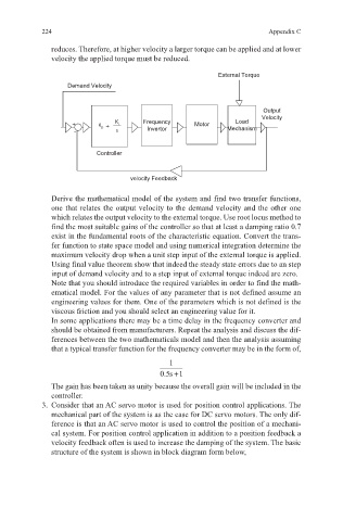
External Torque
Demand Velocity
Output
Velocity
Frequency Load
+ K p + K i Motor
- s Invertor Mechanism
Controller
velocity Feedback
Derive the mathematical model of the system and find two transfer functions,
one that relates the output velocity to the demand velocity and the other one
which relates the output velocity to the external torque. Use root locus method to
find the most suitable gains of the controller so that at least a damping ratio 0.7
exist in the fundamental roots of the characteristic equation. Convert the trans-
fer function to state space model and using numerical integration determine the
maximum velocity drop when a unit step input of the external torque is applied.
Using final value theorem show that indeed the steady state errors due to an step
input of demand velocity and to a step input of external torque indeed are zero.
Note that you should introduce the required variables in order to find the math-
ematical model. For the values of any parameter that is not defined assume an
engineering values for them. One of the parameters which is not defined is the
viscous friction and you should select an engineering value for it.
In some applications there may be a time delay in the frequency converter and
should be obtained from manufacturers. Repeat the analysis and discuss the dif-
ferences between the two mathematicals model and then the analysis assuming
that a typical transfer function for the frequency converter may be in the form of,
1
05.s 1+
The gain has been taken as unity because the overall gain will be included in the
controller.
3. Consider that an AC servo motor is used for position control applications. The
mechanical part of the system is as the case for DC servo motors. The only dif-
ference is that an AC servo motor is used to control the position of a mechani-
cal system. For position control application in addition to a position feedback a
velocity feedback often is used to increase the damping of the system. The basic
structure of the system is shown in block diagram form below,